
User's Guide

PureWave Quantum 6600 Installation Guide v2.1
Page 23
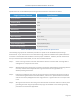
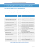
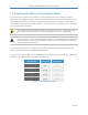
Specifications for the PureWave Quantum Surge Protection Kit are summarized in Table 6.
Surge Protector Feature
Specifications
Surge Capabilities
IEC 1000-4-5, 8/20μs @ 10kA
Frequency Range
2-6GHz
Return Loss
> 20dB
Insertion Loss
≤ 0.2dB
RF Power Limit
10 Watts
Max Temperature
-40
o
C to +85
o
C
Relative Humidity
0-100% condensing
Surge Throughput Energy
≤ 0.5μJ (6kV/3kA 8/20μs)
Peak Let-Through Voltage
±3V (6kV/3kA 8/20μs)
Table 6: PureWave Quantum Surge Protection Kit Specifications
The following surge protector installation procedure is specific to the PureWave Quantum Surge
Protection Kit. If you have chosen to use alternative surge protection hardware then please follow the
instructions received with that hardware to ensure proper installation. However, we still recommend
that you review the procedure below, as much of it will still be relevant.
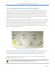
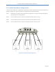
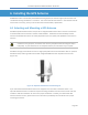
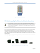
Step 1:
Screw one surge arrestor onto each base station antenna connector ANT-1 through ANT-6
and tighten to a torque of 12-15 in-lbs.
Step 2:
Weatherproof each surge arrestor connection to the base station before proceeding with the
next step. Please refer to Appendix A for a general discussion and guidelines on
weatherproofing connections.
Step 3:
Place the grounding bar over the row of surge arrestors such that the two ground terminal
screws are facing the bottom of the base station, and secure in place with the lock washers
and nuts that came packaged with each surge protector. Tighten each nut to a torque of 30
in-lbs.
Step 4:
Wire ground connections from the ground bar terminals to the base station connector panel
grounding terminal using the provided crimp rings and hardware. Base station grounding
procedures are covered in Appendix A.