
User's Manual

UL Collaborative Spatial Multiplexing*, UL SDMA* (* future)
Air Link Optimization HARQ, CTC
Table 4: Radio and PHY Specifications
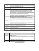
2.3.2.1 Receiver Sensitivity
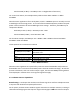
Table 5 presents typical receiver sensitivity specs of the Quantum 6600 base station. Note that
sensitivity will be correspondingly less on models with fewer than 6 antennas. Note that the
values presented are measured over the entire channel bandwidth, as opposed to WiMAX
Radio Conformance Test (RCT) type measurements, which are measured over only a fraction of
the channel bandwidth.
Typical 6-Ant Rx Sensitivity
AWGN, 10
-6
BER, Full Band, in dBm
UL MCS (CTC) 5MHz 10MHz
QPSK-1/2 -105.0 -102.0
QPSK-3/4 -102.0 -99.0
16QAM-1/2 -99.8 -96.8
16QAM-3/4 -96.1 -93.1
64QAM-1/2 -95.1 -92.1
64QAM-2/3 -90.9 -87.9
64QAM-3/4 -90.2 -87.2
64QAM-5/6 -87.0 -84.0
Table 5: Typical Rx Sensitivity
2.3.2.2 Computing EIRP Power
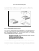
Effective Isotropic Radiated Power (EIRP) refers to the transmit power radiating out of the
antenna. The accurate computation of EIRP is essential to proper network planning and to
ensuring that the system meets local and regional maximum power regulations.
As indicated in Table 4, the average Tx power output at each base station antenna connector is
33dBm. The average EIRP per antenna is computed as follows:
Ave EIRP per Ant (in dBm) = Ave Tx Pwr per Ant + Ant Gain – Cable and Connector Loss
For example, if deployed with a 14dBi antenna connected to the base station with only a few
feet of cable, the average EIRP per Antenna might be 33dBm + 14dBi – 1dB = 46dBm.
The total average EIRP of the base station with all antennas combined can then be computed as
follows: