
User's Manual

GND
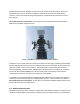
This M5 screw provides a ground connection point to the base station. It is
the installer’s responsibility to ensure that the unit is professionally grounded
and complies with all relevant local codes.
GPS
N-type connector for mandatory external GPS antenna. 3.3V power on center
pin.
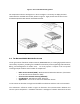
ETH-1
This Gigabit Ethernet port serves as the data traffic backhaul
Interface and also provides for in-band management of the base station.
Note that this port may be physically routed directly to the operator’s
network equipment, or it may be daisy-chained through additional PureWave
Quantum sectors by routing it to another unit’s ETH-2 port.
Cat-5 (RJ-45), Single-Mode Fiber (HartingPull/Han 3 A), and Multi-Mode (LC
duplex) Fiber options are available for the ETH-1 port.
ETH-2
This Gigabit Ethernet port serves as an incoming daisy-chain port from a
neighboring sector, and may be used for out-of-band management of the
base station. It may also be used to connect to an external device, such as a
web camera. Daisy-chained traffic is aggregated and passed through the ETH-
1 port.
Cat-5 (RJ-45), Single-Mode Fiber (HartingPull/Han 3 A), and Multi-Mode (LC
duplex) Fiber options are available for the ETH-2 port.
CONSOLE
RJ-45 based RS-232 port for CLI control via a console.
Defaults settings are 38400, 8, None, 1, Xon/Xoff.
ANT 1-6
N-type Tx / Rx Antenna Ports. Note that different models have differing
numbers of antenna ports.
BH 1-2
N-type Tx / Rx Wireless Backhaul Antenna Ports. These ports are reserved for
future use and, if present, should be tightly capped and weather-proofed.
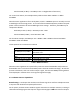
Table 2: Description of Connectors
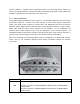
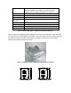
LED Function
STATUS
Green - BS is up and running normally. No faults detected.
Blinking Red – System booting up, or system is temporarily down.
Solid Red - Fault detected.
Off – LEDs disabled or Power is off. Fault detected if POWER LED is Green, but STATUS LED is
Off.
LINK/ACT
Solid Green – Connected to an Ethernet switch.
Blinking Green – Ethernet packet activity.
Off – LEDs disabled or no Ethernet activity detected.
POWER
Green – Power is being supplied to the BS.
Off – LEDs disabled or no power is being supplied to the BS.
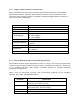
Table 3: Description of LEDs