
User's Manual

specific hardware. Together these components deliver the processing power required to
realize the high-performance required by today’s demanding applications, while yielding the
flexibility to support future functionality as the needs arise.
2.3.1 Physical Interfaces
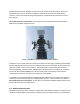
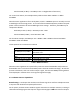
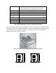
The PureWave Quantum 6600 is shown in Figure 2. The PureWave Quantum product’s flexible
architecture allows for a number of product variants to suite almost limitless deployment
needs. The model shown includes six antenna ports, two additional ports for future wireless
backhaul options, Gigabit Ethernet backhaul ports, and a DC power connector. Single or Multi-
Mode Fiber backhaul and AC power options are also available. As the configuration of
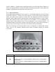
individual base station models vary, so will the appearance of the connector panel. All
PureWave Quantum base stations include an RS-232 console port, a GPS antenna connector, a
ground screw, and three high-intensity LEDs. They are described in 2 and Table 3.
Note that Installation and weatherproofing must be completed by a professional installer.
Please refer to the PureWave Quantum Base Station Installation Manual for detailed
instructions.
Figure 2: PureWave Quantum 6600
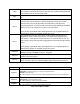
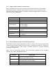
Connector Function
PWR
-48VDC or 110/220V AC power source inputs for the unit.
DC power connector: LTW BB-04PMMS-LC7001 (chassis), LTW BB-04BFFA-
LL7001 (mate)
AC power connector: LTW BB-03PMMS-LC7001 (chassis), LTW BB-03BFFA-
LL7001 (mate)