
User's Manual Part 1

Quantum 1000 Base Station User
Figure
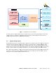
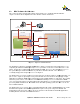
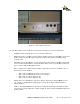
Once the Base Station enclosure has been mounted, the following connections must be made.
• POWER
: Provides the DC power source for
•
GND: This provides a ground connection point for the Base Station. It is important to ensure that
the Base Station is professionally grounded and complies with all local relevant grounding
electrical codes.
• GPS ANT: This port prov
ides the connection between the GPS antenna (external) and the GPS
receiver module (internal). GPS is used by the Base Station Sector to synchronize its TDD gate
to those of Base Stations in neighboring cells.
• ANT 1 – ANT 4:
This is where the Base Statio
antenna ports are described as:
o
ANT 1: This is a transmit (Tx) and a receive (Rx) port.
o
ANT 2: This is a transmit (Tx) and a receive (Rx) port.
o
ANT 3: This is a receive (Rx) port only.
o
ANT 4: This is a recei
•
RS232: This is the serial interface to the Base Station. This interface will be primarily used for
“out of the box” configuration and debug purposes when directed by PureWave Technical
Support Engineers.
• E-NET 1: This
Gigabit Ethernet
connected to the Service Provider’s network equipment.
the Base Station.
Quantum 1000 Base Station User
Guide
Rev 1.1, Page
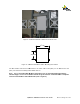
Figure
11 - Base Station Connected
Once the Base Station enclosure has been mounted, the following connections must be made.
: Provides the DC power source for
the Base Station unit.
GND: This provides a ground connection point for the Base Station. It is important to ensure that
the Base Station is professionally grounded and complies with all local relevant grounding
ides the connection between the GPS antenna (external) and the GPS
receiver module (internal). GPS is used by the Base Station Sector to synchronize its TDD gate
to those of Base Stations in neighboring cells.
This is where the Base Statio
n is physically connected to an antenna.
antenna ports are described as:
ANT 1: This is a transmit (Tx) and a receive (Rx) port.
ANT 2: This is a transmit (Tx) and a receive (Rx) port.
ANT 3: This is a receive (Rx) port only.
ANT 4: This is a recei
ve (Rx) port only.
RS232: This is the serial interface to the Base Station. This interface will be primarily used for
“out of the box” configuration and debug purposes when directed by PureWave Technical
Gigabit Ethernet
port provides the data traffic backhaul interface that should be
connected to the Service Provider’s network equipment.
This port allows in-
band management
Rev 1.1, Page
19 of 70
Once the Base Station enclosure has been mounted, the following connections must be made.
GND: This provides a ground connection point for the Base Station. It is important to ensure that
the Base Station is professionally grounded and complies with all local relevant grounding
ides the connection between the GPS antenna (external) and the GPS
receiver module (internal). GPS is used by the Base Station Sector to synchronize its TDD gate
n is physically connected to an antenna.
The 4
RS232: This is the serial interface to the Base Station. This interface will be primarily used for
“out of the box” configuration and debug purposes when directed by PureWave Technical
port provides the data traffic backhaul interface that should be
band management
of