TSD402 Intruder Alarm Control Panel & Speech Dialler UNSET 1 4 2 5 3 6 7 8 0 9 HOME AWAY TSD402 Installation & Programming Instructions
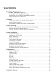
Contents Regulatory Requirements . . . . . . . . . . . . . . . . . . . . . . . . . . . . . . . . . . . . . 1 General, Application & Approval . . . . . . . . . . . . . . . . . . . . . . . . . . . . . . . . . . . . . . . Connections & Compatibility with PABXs . . . . . . . . . . . . . . . . . . . . . . . . . . . . . . . . . Responsibility for Connection To Telephone Network . . . . . . . . . . . . . . . . . . . . . . . . Ringer Equivalence Number (REN) . . . . . . . . . . . . . . . . . . . . . . . . . . . . .
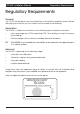
TSD402 Installation Manual Regulatory Requirements Regulatory Requirements General The TSD402 control panel must be installed by a electrically competent person. Before attempting to install the unit, the installer must be aware of the following: Application The TSD402 is suitable for connection to the following types of telephone networks: • Direct exchange lines (PSTN) supporting DTMF (Tone dialling) or Loop Disconnect (Pulse Dialling).
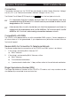
Regulatory Requirements TSD402 Installation Manual Connections Connection terminals on the TSD402 are described as either "Safety Extra-Low Voltage" circuits (S.E.L.V) or "Telecommunications Network Voltage" circuits (T.N.V). The Printed Circuit Board (PCB) layout on page 11 shows the two types of circuits. + + It is important that the installer ensures that T.N.V connections are only connected to the PSTN and S.E.L.V circuits are only connected to other circuits designated as S.E.L.V circuits.
TSD402 Installation Manual Overview Overview Introduction The TSD402 is a 5 zone (+ Final Exit) control panel with an integral Speech Dialler. It is ideally suited for domestic and small commercial installations, which require additional security through the communication of audio alarm messages over the telephone line.
Overview TSD402 Installation Manual The TSD402 incorporates a 3 button set facility which simplifies the setting and part-setting of the system for user. When the user wishes to full set the system, they simply enter the first 2 digits of their passcode followed by the AWAY key. To part-set the system, they simply enter the first 2 digits of their passcode followed by the HOME key. When unsetting the system the user must enter all 4 digits of the passcode.
TSD402 Installation Manual Overview repeated with the acknowledgement "bleeps" again. If the call is not acknowledged at the end of the fifth play of the message the unit abandons that call and attempts the next telephone number. This procedure is repeated three times in sequence for all three telephone numbers. If no acknowledgement has been received then the speech dialler shuts down.
System Planning TSD402 Installation Manual System Planning General The TSD402 is a flexible system, but care must be taken in planning the installation to provide maximum protection with minimum installation effort. Survey the household and determine where each security device is to be fitted. Wherever possible, try to conceal wiring (e.g., in the loft, under carpets or floorboards and inside cupboards). Commit the system design to paper for easy reference.
TSD402 Installation Manual System Planning External Sounder The External Sounder should be mounted as high as possible so that it is visible and out of reach to potential intruders. A six core cable is required for connection to the sounder, it should enter directly through the wall and into the sounder via the cable entries in the back plate. However, if the cable is run over the surface to the sounder then it should be protected (e.g., the cable may be run in aluminium conduit).
System Planning TSD402 Installation Manual Final Exit This is the point at which the user leaves and enters the premises (normally the front door). When setting the system the user must leave the premises via the exit route and through the Final Exit zone. When re-entering the premises the user must activate the Final Exit zone to start the entry timer which allows the user time to gain access to the control panel to unset the system.
TSD402 Installation Manual System Installation System Installation Control Panel layout Mains Cable Entry Cable Entry PCB Supports Loudspeaker (Under PCB) Holders for spare fuses PCB Fused Terminal Block (200mA) PCB Clips Transformer + Cover Clips Battery 2.1 Ah max. Figure 1 TSD402 Control Panel layout Installing the Control Panel + For your safety, installation of the TSD402 must be conducted in the following sequence.
System Installation TSD402 Installation Manual b) Pull down the plastic clip at the bottom right hand corner of the PCB and gently lift the PCB forward. c) Repeat with the plastic clip at the bottom left hand corner of the PCB. d) The bottom of the PCB will then swing forward and the whole PCB will come away from the base. 3 Hold the base in the required position and mark the centre of the keyhole positions. Remove the base, then drill and plug the holes.
TSD402 Installation Manual System Installation Control Panel PCB Layout Factory Restart Pins Auxiliary Trigger Input Polarity Selector Bell Fuse (1 Amp) JP3 Flying Leads to T ransformer FACT OR Y REST AR T Zone Connections (S.E.L.V Circuit) A P F Auxiliary Dialler Trigger Inputs (S.E.L.V Circuit) 16 Character LCD Display Remote Keypad Interface socket (S.E.L.V Circuit) INT.
System Installation TSD402 Installation Manual Connections & Controls (Cont.) EXT. VOLUME (VR1) - If an extension loudspeaker is connected to the control panel, the volume of keypad bleeps, chime, entry and exit tones may be adjusted using this control (clockwise to increase). Alarm tones are always full volume. INT. VOLUME (VR2) - This controls the volume of keypad bleeps, chime, entry and exit tones from the internal loudspeaker (clockwise to increase).
TSD402 Installation Manual System Installation ZONE 5 (PA) - This pair of terminals may be connected to any type of normally closed detection device. When activated during a set condition, a full alarm is generated. It is also possible to program the zone as "PA" this allows the zone to be connected to any type of normally closed PA buttons. The tamper loop should be connected in series with other loops across the terminals marked AUX TAMPER (see Connection Diagram).
System Installation TSD402 Installation Manual Connections & Controls (Cont.) TRG - - This terminal provides the switched negative bell trigger output (max. 500mA). It should be connected to the -ve bell trigger input on the external sounder or SAB module. The output may be programmed for SAB or SCB operation: SAB When programmed as SAB, the output will switch to 0V on alarm. SCB When programmed as SCB, the output provides a 0V hold off, which is removed on alarm.
TSD402 Installation Manual System Installation Connection Diagram External Sounder TSD402 TRIGGER STROBE HOLD OFF + HOLD OFF TAMPER RETURN - ALARM PIR To Zone 1 ALM RST TRG STB+ - H/O TMP AUX TAMPER L/S + AUX 12V - Terminal Strip (Not supplied) TAMPER 0V +12V To AUX 12V To AUX 12V + ZONE 5 (P A) ZONE 4 (Fire) ALARM To Zone 2 ZONE 3 (K/Sw) PIR TAMPER ZONE 2 (Access) 0V +12V To AUX 12V To AUX 12V + ZONE 1 (Access) FINAL EXIT To Zone 3 Surface Contact To FINAL EXIT Flush Contact To Zon
System Installation TSD402 Installation Manual Installing a TS400 Remote keypad Up to four TS400 remote keypads may be connected to the TSD402 control panel. The remote keypad is supplied with an interface PCB which plugs onto the main PCB. Remote keypad(s) may be sited up to a maximum of 50 metres from the control panel using a six-core cable for connections. + The TS400 remote keypad is only suitable for setting, part-setting, unsetting and limited programming functions.
TSD402 Installation Manual System Installation TRIG POLARITY - TRIG POLARITY + - AUX 12V TSD402 + AUX 12V - + TRIGGER A P F N.C. Loop 1KW resistor N.O. Loop TSD402 12V on alarm N.O. Loop TRIGGER A P F N.C.
System Installation TSD402 Installation Manual Pre Power-Up Checks Before applying any power to the system, give the system one final check to ensure that: 1 The telephone lead is unplugged from the telephone socket. 2 The wiring and connections conforms to the requirements detailed in this manual. 3 All system cables are kept clear of mains supply cables, telephone cables and R.F. cables. It is recommended that cable ties be used to keep cables separated.
TSD402 Installation Manual System Installation Initial Power-Up (Cont.) 2 Switch on the 240V mains supply and remove the screwdriver blade. The internal alarm will bleep every 30 seconds the display will show: CFT. 3 Connect the standby battery. If the display shows: BATT. FLT and the internal alarm sounds, then the battery may have been incorrectly connected or its voltage is below 8V. Disconnect the battery immediately and reconnect or replace as appropriate.
Programming TSD402 Installation Manual Programming Programming Menus There are two programming menus within the system. The engineer's programming menu and the user programming menu. The figure below shows the structure of both programming menus, however the engineers programming menu is only covered in full detail within this manual. For full details on the user programming, see User Manual.
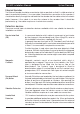
TSD402 Installation Manual Programming Program Zones (key 1 ) The TSD402 zones may be programmed so that they perform different functions. The zones types are as follows: Night (N) - Zones 1-5 may be programmed as a Night zone, this type of zone will only generate a full alarm when activated during a set condition. If during a full alarm condition the speech dialler Alarm channel is programmed to report, it will activate and send the Alarm message.
Programming TSD402 Installation Manual Program Zones (Cont.) 1 Ensure that the "ENGR. OPTION -" is displayed. Press 1 to select Program Zones. 2 Press keys 1 to 6 to toggle between the two options for each zone (as Shown Below). 3 When completed, press [ to accept, a two tone acceptance tone will be heard.
TSD402 Installation Manual Programming View Event Log (Cont.) 1 Ensure that the "ENGR. OPTION -" is displayed. Press 2 to select the View Log option. 2 Press the [ key to move backwards through the Log. 3 When completed, press ] to abandon the View Log option. Walk Test (key 3 ) The Walk Test option allows the engineer to test the function of all detection zones without causing an alarm. As each zone is activated the zone number is displayed and the internal sounders generate a two-tone sound.
Programming TSD402 Installation Manual Entry Time (key 5 ) When the entry procedure is initiated, the Entry Timer is started and the display counts down the remaining time. If a valid user passcode is not entered when the timer reaches zero, a full alarm tone is generated from the internal sounders only and the timer is restarted. If a valid user passcode is not entered when the timer reaches zero for the second time the external sounder is activated. The timer may be set between 1 and 255 seconds.
TSD402 Installation Manual Programming Remote Reset Number (Cont.) The "Remote Reset" code is generated using an algorithm identified by a 3 digit number. Alternative algorithms may be selected but these must correspond to that used by the alarm company otherwise the "Remote Reset" code will be incorrect. The "Remote Reset" feature may be disabled altogether by setting the number to "000" 1 Ensure that the "ENGR. OPTION -" is displayed. Press 8 to select the Remote Reset Number option.
Programming Re-arm Options TSD402 Installation Manual 1 re-arms (1) When an alarm occurs, the internal and external sounders are operated for the length of the bell duration. At the end of this time the alarm is silenced and the all zones are re-armed. Any zones that are active will be automatically isolated until they return to their healthy state.
TSD402 Installation Manual Programming System Options (Cont.) 1 Ensure that the "ENGR. OPTION -" is displayed. Press 9 to select System Options. 2 Press keys 1 to 7 to toggle between the two settings for each option (as Shown Below). 3 When completed, press [ to accept, a two tone acceptance tone will be heard.
Programming TSD402 Installation Manual Returning to the Unset Mode (key ] ) Once all the engineer programming is completed the system can be returned to the unset mode by pressing the ] key. However since the speech dialler has not yet been programmed the display will still show the "PLEASE RE-RECORD" message. This will be cleared when one or more of the speech dialler messages have been recorded (see User Manual for full details).
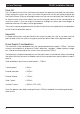
TSD402 Installation Manual Installation Record Installation Record Zone Type Location Chime Home 1 Night / Access On / Off Armed / Omitted 2 Night / Access On / Off Armed / Omitted 3 Night / keyswitch On / Off Armed / Omitted 4 Night / Fire On / Off Armed / Omitted 5 Night / P.A.
Key Function Action Options 1 Program Zones Press 1-6 to toggle zone types Press ] to end 2 View Log Press [ to advance Press ] to end 3 Walk Test Activate detectors Press ] to end 4 Exit Time Enter 3 digit time Press [ to accept Enter time between 001 - 255 (seconds) 5 Entry Time Enter 3 digit time Press [ to accept Enter time between 001 - 255 (seconds) 6 Bell Duration Enter 3 digit time Press [ to accept Enter time between 000 - 255 (minutes) Note: 000 = Continuous 7 Change Engi