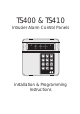
TS400 & TS410 Intruder Alarm Control Panels 1 2 UNSET 3 4 TAMPER FINAL EXIT 5 1 2 3 4 5 6 7 8 9 HOME 0 AWAY Installation & Programming Instructions
TS400/TS410 Installation Instructions Contents Overview Introduction . . . . . . . . . . . . . . . . . . . . . . . . . 3 TS400 Features . . . . . . . . . . . . . . . . . . . . . . . 3 TS410 Features . . . . . . . . . . . . . . . . . . . . . . . 3 Specifications . . . . . . . . . . . . . . . . . . . . . . . . 3 TS400 Control Panel . . . . . . . . . . . . . . . . . 3 TS410 Control Panel . . . . . . . . . . . . . . . . . 3 Remote Keypad . . . . . . . . . . . . . . . . . . . .
TS400/TS410 Installation Instructions Overview Overview Introduction The TS400 and TS410 are 6 zone microprocessor based intruder alarm control panels with 5 programmable zones and a dedicated Final Exit zone. The ease of operation for setting and unsetting lends itself ideally to domestic and smaller commercial installations.
Planning The Installation TS400/TS410 Installation Instructions Planning The Installation General The TS400 and TS410 are flexible systems, but care must be taken in planning the installation to provide maximum protection with minimum effort. Survey the household and determine where each security device is to be fitted. Wherever possible, try to conceal wiring (e.g., in the loft, under carpets or floorboards and inside cupboards). Commit the system design to paper for future reference.
TS400/TS410 Installation Instructions Detection Devices There are several types of detection devices available which are suitable for domestic installations as follows: Passive Infra-Red (PIR) A detector which detects movement of an intruder by the change in infra-red body heat. When fitting PIRs, refer to the installation instructions supplied with the unit. In general there are two types of PIR "Standard" and "Latching".
System Installation TS400/TS410 Installation Instructions System Installation Installing the TS400 Control Panel 1. Remove the screw from the top of the control panel and lift away the front cover. 2. Ensure that there is no battery in the housing, then remove the circuit board as follows: (a) Disconnect the yellow leads from the transformer and remove the connections to the internal loudspeaker.
+ TS400/TS410 Installation Instructions System Installation The mains cable must enter the control panel through its own cable entry and must not be mixed with other cables. 3. Hold the control panel back box in the required position (keyhole to the top) and mark the centre of the keyhole position. Remove the back box, drill and plug the hole. 4. Screw a No 10 screw into the plugged hole. Re-position the back box and mark the remaining securing holes. Remove the back box, drill and plug the holes. 5.
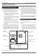
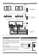
System Installation TS400/TS410 Installation Instructions PCB Layout Tamper switch ALM - VOLUME Home alarm inhibit link 1 2 3 4 UNSET TAMP F/E 5 Factory Restart Pins FACTORY RESTART Remote Keypad Interface Connector (1AMP) AUX 12V Leads to transformer HOME ALM INHIBIT Bell (1AMP) Zone connections RSTTRG STB + H/O - TMP AUX L/S AUX 12V FIRE K'SW ACCESS ACCESS P.A.
TS400/TS410 Installation Instructions System Installation To tamper loop for other zones AUX TAMPER ZONE Connecting several flush contacts per zone Flush Contact Flush Contact To tamper loop for other zones AUX TAMPER ZONE Surface Contact Surface Contact LATCH 0V +12V TAMPER ALARM LATCH +12V 0V Program [RST-] as SW 12V PIR RST - TAMPER PIR ALARM Connecting several suface contacts per zone To tamper loop for other zones AUX TAMPER AUX 12V + - Connecting several PIRs per zone ZONE
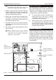
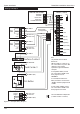
System Installation TS400/TS410 Installation Instructions Wiring Example External Sounder TS400 / TS410 TRIGGER STROBE HOLD OFF + HOLD OFF TAMPER RETURN - ALARM PIR To ZONE 1 R37 ALM RST TRG STB+ - H/O TMP AUX TAMPER L/S + AUX 12V - Terminal strip (not supplied) TAMPER 0V +12V To AUX -12V To AUX +12V ZONE 5 (P A) ZONE 4 (Fire) ALARM PIR To ZONE 2 ZONE 3 (K/Sw) TAMPER ZONE 2 (Access) 0V +12V To AUX -12V To AUX +12V ZONE 1 (Access) FINAL EXIT To ZONE 3 Surface Contact To FINAL EXIT
TS400/TS410 Installation Instructions Installing a Remote Keypad Ensure that the mains and battery power has been disconnected and proceed as follows: 1. Connect each core of the 6-core cable to the interface terminals "L E D C B A" (make a note of the colours used for each connection). 2. Pass the yellow flying-lead behind the PCB and connect it to the [L/S-] terminal. 3. Plug the Interface board into the interface socket as shown below.
System Installation TS400/TS410 Installation Instructions Extension Loudspeakers Aux 12V Power A 16Ohm extension loudspeaker can be connected between the [L/S-] and [AUX 12V+] terminals. R37 (located in the top left hand corner of the PCB) can be cut to reduce the volume of the internal sounders (alarm is always full volume). 16 Ohm Loudspeaker Figure 9 L/S AUX +12V Speaker Connections ALM- Terminal This terminal is switched negative (100mA) on alarm and is removed when the system is reset.
TS400/TS410 Installation Instructions Initial Power-Up 1. Place a small screwdriver blade between the pins on the control panel PCB, marked FACTORY RESTART (located just below the LEDs).
Programming TS400/TS410 Installation Instructions Programming Programming Menus There are two programming menus within the system. The engineer’s programming menu and the user programming menu. The figure below shows the structure of both programming menus, however the engineers programming menu is only covered in full detail within this manual. For full details on the user options see "User Operating Instructions".
TS400/TS410 Installation Instructions Program Zones The TS400 zones may be programmed so that they perform different functions. The zones types are as follows: Alarm Zones 1- 5 can be programmed as alarm zones, this type of zone will only generate a full alarm when activated during a set condition. Programming ➤ To program zones proceed as follows: 1. Ensure that the engineer’s menu is selected, then press [1] to select program zones. 2.
Programming TS400/TS410 Installation Instructions Exit Time Bell Duration Time This timer sets the delay between the user initiating the setting procedure and the system actually setting. This only applies when the system is programmed to set by "Timed Exit", see "System Options" on page 17. This timer controls the duration of the external sounder when the system is triggered into a full alarm condition. ➤ To program the exit time proceed as follows: 1.
TS400/TS410 Installation Instructions Remote Reset Number The "Engineer Reset" option can be overridden by the user, operating the "Remote Reset" facility. If an alarm is generated the system will respond with a four digit "seed" code which the user quotes to the alarm company. The "seed" code is then entered into a decoder and a unique "Remote Reset" code is generated. This is passed back to the user and, on entering the "Remote Reset" code, the system will reset.
Programming TS400/TS410 Installation Instructions Keyswitch Operation Returning to the Unset Mode The operation of the keyswitch (zone 3) can be programmed as either: AWAY: When keyswitch zone is opened the exit procedure for AWAY set will start and the system will attempt to full set. When the zone is closed the system will unset. HOME: When the key switch zone is opened the exit timer will start and when the timer has expired the system will be part set. When the zone is closed the system will unset.
TS400/TS410 Installation Instructions Testing & Fault Finding Testing & Fault Finding Testing the System Fault Finding Once the system has been installed and fully programmed it can be tested. Before performing any tests it is advisable to warn your neighbours of any tests that involve using the external sounder. If you have carefully followed the installation and wiring instructions and carried out the various checks correctly, your security system will now be fully operational. 1.
Testing & Fault Finding TS400/TS410 Installation Instructions Chart 1 - Zone Faults Enter 4 digit engineer code and then press 3 to select walk test mode Permanent Zone Fault Remove control panel front cover and disable the case tamper switch Relevant zone LED on and pulsed sounder No zone LED's on and sounder is off. Remove wiring from faulty zone and link with a piece of wire. Activate the relevant detector Relevant zone LED still on and pulsed sounder. No zone LED's on and sounder is off.
TS400/TS410 Installation Instructions Testing & Fault Finding Chart 2 - System Will Not Set Enter 4 digit engineer code and then press 3 to select walk test mode Deactivate all detectors & contacts (e.g. close doors etc.) No zone LED's on and sounder is off. Press [0] to exit Walk Test. Zone LED on and Pulse Sounder. See Chart 1 on Zone Faults Press [HOME] or [AWAY] to part set or full set the system. Tamper LED on. Remove control panel cover and disable the case tamper.
Testing & Fault Finding TS400/TS410 Installation Instructions Chart 3 - External Sounder Faults Check PA buttons are not depressed. Ensure that the system is in the unset mode. External siren will not trigger when performing a Bell Test. External Siren sounds continuously. Enter 4 digit engineer code and remove the control panel cover. If zone 5 LED is on, the fault is within the PA circuit. (see chart 1) Remove the wire from the TRGterminal.. Remove the wire from the TRGterminal.
TS400/TS410 Installation Instructions Installation Records Installation Records Zone Programming Zone Type Location Chime Home Config.
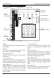
Key Function Action LEDs 1 Zone Types Press [1] - [5] to toggle LEDs on/off. Press [0] to end 1 2 3 4 5 2 View Log Press [1] for newest event Press [4] for oldest event Zone LEDs that light have caused an alarm 3 Walk Test Activate detectors. Press [0] to end When the zone is in alarm the panel will sound and the relevant zone LED will light. 4 5 On Z1 = Access Z2 = Access Z3 = Keyswitch Z4 = Fire Z5 = PA 10 seconds 30 seconds 1 minute 2 minutes Exit Time Press [1] to [4].