
User's Manual
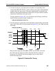

Table Of Contents
- Bookcase
- TABLE OF CONTENTS
- LIST OF FIGURES
- LIST OF TABLES
- About This Manual
- Chapter 1 Introduction
- Chapter 2 Command Dictionary
- Command Summary
- Command Descriptions
- Abort Interrupted Process
- Add Ambiguous Paths
- Add Atpg Constraints
- Add Atpg Functions
- Add Capture Handling
- Add Cell Constraints
- Add Cell Library
- Add Clocks
- Add Cone Blocks
- Add Control Points
- Add Display Instances
- Add Display Loop
- Add Display Path
- Add Display Scanpath
- Add Faults
- Add Iddq Constraints
- Add Initial States
- Add LFSR Connections
- Add LFSR Taps
- Add LFSRs
- Add Lists
- Add Mos Direction
- Add Net Property
- Add Nofaults
- Add Nonscan Handling
- Add Notest Points
- Add Observe Points
- Add Output Masks
- Add Pin Constraints
- Add Pin Equivalences
- Add Pin Strobes
- Add Primary Inputs
- Add Primary Outputs
- Add Random Weights
- Add Read Controls
- Add Scan Chains
- Add Scan Groups
- Add Scan Instances
- Add Scan Models
- Add Slow Pad
- Add Tied Signals
- Add Write Controls
- Analyze Atpg Constraints
- Analyze Bus
- Analyze Control
- Analyze Control Signals
- Analyze Drc Violation
- Analyze Fault
- Analyze Observe
- Analyze Race
- Analyze Restrictions
- Close Schematic Viewer
- Compress Patterns
- Create Initialization Patterns
- Create Patterns
- Delete Atpg Constraints
- Delete Atpg Functions
- Delete Capture Handling
- Delete Cell Constraints
- Delete Clocks
- Delete Cone Blocks
- Delete Control Points
- Delete Display Instances
- Delete Faults
- Delete Iddq Constraints
- Delete Initial States
- Delete LFSR Connections
- Delete LFSR Taps
- Delete LFSRs
- Delete Lists
- Delete Mos Direction
- Delete Net Property
- Delete Nofaults
- Delete Nonscan Handling
- Delete Notest Points
- Delete Observe Points
- Delete Output Masks
- Delete Paths
- Delete Pin Constraints
- Delete Pin Equivalences
- Delete Pin Strobes
- Delete Primary Inputs
- Delete Primary Outputs
- Delete Random Weights
- Delete Read Controls
- Delete Scan Chains
- Delete Scan Groups
- Delete Scan Instances
- Delete Scan Models
- Delete Slow Pad
- Delete Tied Signals
- Delete Write Controls
- Diagnose Failures
- Dofile
- Exit
- Extract Subckts
- Flatten Model
- Flatten Subckt
- Help
- Insert Testability
- Load Faults
- Load Paths
- Macrotest
- Mark
- Open Schematic Viewer
- Read Modelfile
- Read Procfile
- Read Subckts Library
- Redo Display
- Report Aborted Faults
- Report Atpg Constraints
- Report Atpg Functions
- Report AU Faults
- Report Bus Data
- Report Capture Handling
- Report Cell Constraints
- Report Clocks
- Report Cone Blocks
- Report Control Data
- Report Control Points
- Report Core Memory
- Report Display Instances
- Report Drc Rules
- Report Environment
- Report Failures
- Report Faults
- Report Feedback Paths
- Report Flatten Rules
- Report Gates
- Report Hosts
- Report Id Stamp
- Report Iddq Constraints
- Report Initial States
- Report LFSR Connections
- Report LFSRs
- Report Lists
- Report Loops
- Report Mos Direction
- Report Net Properties
- Report Nofaults
- Report Nonscan Cells
- Report Nonscan Handling
- Report Notest Points
- Report Observe Data
- Report Observe Points
- Report Output Masks
- Report Paths
- Report Pin Constraints
- Report Pin Equivalences
- Report Pin Strobes
- Report Primary Inputs
- Report Primary Outputs
- Report Procedure
- Report Pulse Generators
- Report Random Weights
- Report Read Controls
- Report Scan Cells
- Report Scan Chains
- Report Scan Groups
- Report Scan Instances
- Report Scan Models
- Report Seq_transparent Procedures
- Report Slow Pads
- Report Statistics
- Report Test Stimulus
- Report Testability Data
- Report Tied Signals
- Report Timeplate
- Report Version Data
- Report Write Controls
- Reset Au Faults
- Reset State
- Resume Interrupted Process
- Run
- Save Flattened Model
- Save Patterns
- Save Schematic
- Select Iddq Patterns
- Select Object
- Set Abort Limit
- Set Atpg Compression
- Set Atpg Limits
- Set Atpg Window
- Set AU Analysis
- Set Bist Initialization
- Set Bus Handling
- Set Bus Simulation
- Set Capture Clock
- Set Capture Handling
- Set Capture Limit
- Set Checkpoint
- Set Clock Restriction
- Set Clock_off Simulation
- Set Clockpo Patterns
- Set Contention Check
- Set Control Threshold
- Set Decision Order
- Set Dofile Abort
- Set Drc Handling
- Set Driver Restriction
- Set Fails Report
- Set Fault Mode
- Set Fault Sampling
- Set Fault Type
- Set Flatten Handling
- Set Gate Level
- Set Gate Report
- Set Hypertrophic Limit
- Set Iddq Checks
- Set Iddq Strobe
- Set Instancename Visibility
- Set Instruction Atpg
- Set Internal Fault
- Set Internal Name
- Set Interrupt Handling
- Set IO Mask
- Set Learn Report
- Set List File
- Set Logfile Handling
- Set Loop Handling
- Set Multiple Load
- Set Net Dominance
- Set Net Resolution
- Set Nonscan Model
- Set Number Shifts
- Set Observation Point
- Set Observe Threshold
- Set Output Comparison
- Set Output Mask
- Set Pathdelay Holdpi
- Set Pattern Source
- Set Possible Credit
- Set Procedure Cycle_checking
- Set Pulse Generators
- Set Race Data
- Set Rail Strength
- Set Ram Initialization
- Set Ram Test
- Set Random Atpg
- Set Random Clocks
- Set Random Patterns
- Set Random Weights
- Set Redundancy Identification
- Set Schematic Display
- Set Screen Display
- Set Self Initialization
- Set Sensitization Checking
- Set Sequential Learning
- Set Shadow Check
- Set Simulation Mode
- Set Skewed Load
- Set Split Capture_cycle
- Set Stability Check
- Set Static Learning
- Set Stg Extraction
- Set System Mode
- Set Test Cycle
- Set Trace Report
- Set Transition Holdpi
- Set Unused Net
- Set Workspace Size
- Set Xclock Handling
- Set Z Handling
- Set Zhold Behavior
- Set Zoom Factor
- Setup Checkpoint
- Setup LFSRs
- Setup Pin Constraints
- Setup Pin Strobes
- Setup Tied Signals
- Step
- System
- Undo Display
- Unmark
- Unselect Object
- Update Implication Detections
- View
- View Area
- Write Core Memory
- Write Environment
- Write Failures
- Write Faults
- Write Initial States
- Write Library_verification Setup
- Write Loops
- Write Modelfile
- Write Netlist
- Write Paths
- Write Primary Inputs
- Write Primary Outputs
- Write Procfile
- Write Statistics
- Write Timeplate
- Zoom In
- Zoom Out
- Chapter 3 Shell Commands
- Chapter 4 Test Pattern File Formats
- Chapter 5 Distributed FlexTest
- Appendix A Timing Command Dictionary
- Appendix B FlexTest WDB Translation Support
- INDEX
- Send us feedback

FastScan and FlexTest Reference Manual, V8.6_4
B-10
Using wdb2flex Effectively FlexTest WDB Translation Support
The following describes the corresponding wdb2flex control file. You can derive
this control file using the steps listed for obtaining an optimum control file.
set cycle time 250
setup input strobes 75
setup output strobes 95
add input clocks SR0 105 205 CLK
You would issue the following FlexTest commands to specify a test cycle
consistent with this timing. You can derive this test cycle using the steps listed for
obtaining correspondence between the test cycle and the control file.
set test cycle 3
setup pIn constraints nr 1 0
setup pIn strobes 1
add pIn constraints clk sr0 1 1 1
You can use the FlexTest commands for fault simulating the functional pattern
set. You can also invoke FlexTest ATPG on the faults not detected by the stimuli
in the waveform database. Finally, you can reproduce the same timing in any
simulation or ASIC vendor format by using the following timing file:
set force time 100 200 250
set bidi_force time 50 150 225 // for ABUS
set skew_force time “CNTRL” 70 170 230 // for CNTRL
set measure time 95 195 245
Despite all these precautions, there can still be mismatches between the expected
output values in QuickSim II and those in FlexTest. Some of the common causes
of mismatches are:
• Using unit delay simulation with QuickSim II. You should use typical delay
values whenever possible when performing QuickSim II simulations. Unit
delay simulation will give improper results for designs in which the clocks
of different latches and flip-flops have differing numbers of buffers feeding
them.
• Asynchronous loops in the design. If the design has asynchronous loops, set
loop handling to X in the FlexTest simulation. This causes FlexTest to
simulate more unknown values. However, this can potentially cause more
bus contention.