
User's Manual
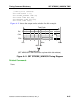
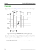
Table Of Contents
- Bookcase
- TABLE OF CONTENTS
- LIST OF FIGURES
- LIST OF TABLES
- About This Manual
- Chapter 1 Introduction
- Chapter 2 Command Dictionary
- Command Summary
- Command Descriptions
- Abort Interrupted Process
- Add Ambiguous Paths
- Add Atpg Constraints
- Add Atpg Functions
- Add Capture Handling
- Add Cell Constraints
- Add Cell Library
- Add Clocks
- Add Cone Blocks
- Add Control Points
- Add Display Instances
- Add Display Loop
- Add Display Path
- Add Display Scanpath
- Add Faults
- Add Iddq Constraints
- Add Initial States
- Add LFSR Connections
- Add LFSR Taps
- Add LFSRs
- Add Lists
- Add Mos Direction
- Add Net Property
- Add Nofaults
- Add Nonscan Handling
- Add Notest Points
- Add Observe Points
- Add Output Masks
- Add Pin Constraints
- Add Pin Equivalences
- Add Pin Strobes
- Add Primary Inputs
- Add Primary Outputs
- Add Random Weights
- Add Read Controls
- Add Scan Chains
- Add Scan Groups
- Add Scan Instances
- Add Scan Models
- Add Slow Pad
- Add Tied Signals
- Add Write Controls
- Analyze Atpg Constraints
- Analyze Bus
- Analyze Control
- Analyze Control Signals
- Analyze Drc Violation
- Analyze Fault
- Analyze Observe
- Analyze Race
- Analyze Restrictions
- Close Schematic Viewer
- Compress Patterns
- Create Initialization Patterns
- Create Patterns
- Delete Atpg Constraints
- Delete Atpg Functions
- Delete Capture Handling
- Delete Cell Constraints
- Delete Clocks
- Delete Cone Blocks
- Delete Control Points
- Delete Display Instances
- Delete Faults
- Delete Iddq Constraints
- Delete Initial States
- Delete LFSR Connections
- Delete LFSR Taps
- Delete LFSRs
- Delete Lists
- Delete Mos Direction
- Delete Net Property
- Delete Nofaults
- Delete Nonscan Handling
- Delete Notest Points
- Delete Observe Points
- Delete Output Masks
- Delete Paths
- Delete Pin Constraints
- Delete Pin Equivalences
- Delete Pin Strobes
- Delete Primary Inputs
- Delete Primary Outputs
- Delete Random Weights
- Delete Read Controls
- Delete Scan Chains
- Delete Scan Groups
- Delete Scan Instances
- Delete Scan Models
- Delete Slow Pad
- Delete Tied Signals
- Delete Write Controls
- Diagnose Failures
- Dofile
- Exit
- Extract Subckts
- Flatten Model
- Flatten Subckt
- Help
- Insert Testability
- Load Faults
- Load Paths
- Macrotest
- Mark
- Open Schematic Viewer
- Read Modelfile
- Read Procfile
- Read Subckts Library
- Redo Display
- Report Aborted Faults
- Report Atpg Constraints
- Report Atpg Functions
- Report AU Faults
- Report Bus Data
- Report Capture Handling
- Report Cell Constraints
- Report Clocks
- Report Cone Blocks
- Report Control Data
- Report Control Points
- Report Core Memory
- Report Display Instances
- Report Drc Rules
- Report Environment
- Report Failures
- Report Faults
- Report Feedback Paths
- Report Flatten Rules
- Report Gates
- Report Hosts
- Report Id Stamp
- Report Iddq Constraints
- Report Initial States
- Report LFSR Connections
- Report LFSRs
- Report Lists
- Report Loops
- Report Mos Direction
- Report Net Properties
- Report Nofaults
- Report Nonscan Cells
- Report Nonscan Handling
- Report Notest Points
- Report Observe Data
- Report Observe Points
- Report Output Masks
- Report Paths
- Report Pin Constraints
- Report Pin Equivalences
- Report Pin Strobes
- Report Primary Inputs
- Report Primary Outputs
- Report Procedure
- Report Pulse Generators
- Report Random Weights
- Report Read Controls
- Report Scan Cells
- Report Scan Chains
- Report Scan Groups
- Report Scan Instances
- Report Scan Models
- Report Seq_transparent Procedures
- Report Slow Pads
- Report Statistics
- Report Test Stimulus
- Report Testability Data
- Report Tied Signals
- Report Timeplate
- Report Version Data
- Report Write Controls
- Reset Au Faults
- Reset State
- Resume Interrupted Process
- Run
- Save Flattened Model
- Save Patterns
- Save Schematic
- Select Iddq Patterns
- Select Object
- Set Abort Limit
- Set Atpg Compression
- Set Atpg Limits
- Set Atpg Window
- Set AU Analysis
- Set Bist Initialization
- Set Bus Handling
- Set Bus Simulation
- Set Capture Clock
- Set Capture Handling
- Set Capture Limit
- Set Checkpoint
- Set Clock Restriction
- Set Clock_off Simulation
- Set Clockpo Patterns
- Set Contention Check
- Set Control Threshold
- Set Decision Order
- Set Dofile Abort
- Set Drc Handling
- Set Driver Restriction
- Set Fails Report
- Set Fault Mode
- Set Fault Sampling
- Set Fault Type
- Set Flatten Handling
- Set Gate Level
- Set Gate Report
- Set Hypertrophic Limit
- Set Iddq Checks
- Set Iddq Strobe
- Set Instancename Visibility
- Set Instruction Atpg
- Set Internal Fault
- Set Internal Name
- Set Interrupt Handling
- Set IO Mask
- Set Learn Report
- Set List File
- Set Logfile Handling
- Set Loop Handling
- Set Multiple Load
- Set Net Dominance
- Set Net Resolution
- Set Nonscan Model
- Set Number Shifts
- Set Observation Point
- Set Observe Threshold
- Set Output Comparison
- Set Output Mask
- Set Pathdelay Holdpi
- Set Pattern Source
- Set Possible Credit
- Set Procedure Cycle_checking
- Set Pulse Generators
- Set Race Data
- Set Rail Strength
- Set Ram Initialization
- Set Ram Test
- Set Random Atpg
- Set Random Clocks
- Set Random Patterns
- Set Random Weights
- Set Redundancy Identification
- Set Schematic Display
- Set Screen Display
- Set Self Initialization
- Set Sensitization Checking
- Set Sequential Learning
- Set Shadow Check
- Set Simulation Mode
- Set Skewed Load
- Set Split Capture_cycle
- Set Stability Check
- Set Static Learning
- Set Stg Extraction
- Set System Mode
- Set Test Cycle
- Set Trace Report
- Set Transition Holdpi
- Set Unused Net
- Set Workspace Size
- Set Xclock Handling
- Set Z Handling
- Set Zhold Behavior
- Set Zoom Factor
- Setup Checkpoint
- Setup LFSRs
- Setup Pin Constraints
- Setup Pin Strobes
- Setup Tied Signals
- Step
- System
- Undo Display
- Unmark
- Unselect Object
- Update Implication Detections
- View
- View Area
- Write Core Memory
- Write Environment
- Write Failures
- Write Faults
- Write Initial States
- Write Library_verification Setup
- Write Loops
- Write Modelfile
- Write Netlist
- Write Paths
- Write Primary Inputs
- Write Primary Outputs
- Write Procfile
- Write Statistics
- Write Timeplate
- Zoom In
- Zoom Out
- Chapter 3 Shell Commands
- Chapter 4 Test Pattern File Formats
- Chapter 5 Distributed FlexTest
- Appendix A Timing Command Dictionary
- Appendix B FlexTest WDB Translation Support
- INDEX
- Send us feedback

FlexTest WDB Translation Support Control File
FastScan and FlexTest Reference Manual, V8.6_4
B-3
The Setup Output Strobes command sets the default strobe point for all output
waveforms. Keeping the test cycle in mind, you should specify a time before the
clock is active, but after the output data is stable. Typically, you should not strobe
at the clock edges if the design contains latches, because timing problems could
result.
ADD INput Strobes number input_list
The Add Input Strobes command changes the sampling time of one or more
specific inputs from the default value to the specified number. Typically, you
would use Setup Input Strobes to set the strobe time for all inputs and only use this
command if you had a special case that required strobing a certain pin at a
different time.
ADD OUtput Strobes number output_list
The Add Output Strobes command changes a particular output sampling time
from the default to the specified number. Typically, you would use Setup Output
Strobes to set the strobe time for all outputs and only use this command if you had
a special case that required strobing a certain pin at a different time.
ADD INput Clocks format strobe1 strobe2 input_list
The Add Input Clocks command sets the clocks’ format and strobe points. The
available format literals are R0, R1, SR0, SR1. The strobe points sample the
waveform and perform error checking. Strobe1 must occur when the clock is on
and strobe2 must occur when the clock is off. For the SR0 and SR1 formats, if the
two strobe sample points have different values, there is a pulse in that cycle. The
utility error checks all formats to make certain that the pulse matches the format. It
issues a warning if it encounters any inconsistencies. Thus, the stimulus generated
in FlexTest table format is guaranteed to be correct. For instance, if the input
stimulus for a R0 waveform is missing a pulse in a cycle, FlexTest requires the
translator to insert one.