
User's Manual
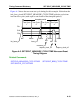
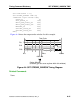
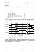
Table Of Contents
- Bookcase
- TABLE OF CONTENTS
- LIST OF FIGURES
- LIST OF TABLES
- About This Manual
- Chapter 1 Introduction
- Chapter 2 Command Dictionary
- Command Summary
- Command Descriptions
- Abort Interrupted Process
- Add Ambiguous Paths
- Add Atpg Constraints
- Add Atpg Functions
- Add Capture Handling
- Add Cell Constraints
- Add Cell Library
- Add Clocks
- Add Cone Blocks
- Add Control Points
- Add Display Instances
- Add Display Loop
- Add Display Path
- Add Display Scanpath
- Add Faults
- Add Iddq Constraints
- Add Initial States
- Add LFSR Connections
- Add LFSR Taps
- Add LFSRs
- Add Lists
- Add Mos Direction
- Add Net Property
- Add Nofaults
- Add Nonscan Handling
- Add Notest Points
- Add Observe Points
- Add Output Masks
- Add Pin Constraints
- Add Pin Equivalences
- Add Pin Strobes
- Add Primary Inputs
- Add Primary Outputs
- Add Random Weights
- Add Read Controls
- Add Scan Chains
- Add Scan Groups
- Add Scan Instances
- Add Scan Models
- Add Slow Pad
- Add Tied Signals
- Add Write Controls
- Analyze Atpg Constraints
- Analyze Bus
- Analyze Control
- Analyze Control Signals
- Analyze Drc Violation
- Analyze Fault
- Analyze Observe
- Analyze Race
- Analyze Restrictions
- Close Schematic Viewer
- Compress Patterns
- Create Initialization Patterns
- Create Patterns
- Delete Atpg Constraints
- Delete Atpg Functions
- Delete Capture Handling
- Delete Cell Constraints
- Delete Clocks
- Delete Cone Blocks
- Delete Control Points
- Delete Display Instances
- Delete Faults
- Delete Iddq Constraints
- Delete Initial States
- Delete LFSR Connections
- Delete LFSR Taps
- Delete LFSRs
- Delete Lists
- Delete Mos Direction
- Delete Net Property
- Delete Nofaults
- Delete Nonscan Handling
- Delete Notest Points
- Delete Observe Points
- Delete Output Masks
- Delete Paths
- Delete Pin Constraints
- Delete Pin Equivalences
- Delete Pin Strobes
- Delete Primary Inputs
- Delete Primary Outputs
- Delete Random Weights
- Delete Read Controls
- Delete Scan Chains
- Delete Scan Groups
- Delete Scan Instances
- Delete Scan Models
- Delete Slow Pad
- Delete Tied Signals
- Delete Write Controls
- Diagnose Failures
- Dofile
- Exit
- Extract Subckts
- Flatten Model
- Flatten Subckt
- Help
- Insert Testability
- Load Faults
- Load Paths
- Macrotest
- Mark
- Open Schematic Viewer
- Read Modelfile
- Read Procfile
- Read Subckts Library
- Redo Display
- Report Aborted Faults
- Report Atpg Constraints
- Report Atpg Functions
- Report AU Faults
- Report Bus Data
- Report Capture Handling
- Report Cell Constraints
- Report Clocks
- Report Cone Blocks
- Report Control Data
- Report Control Points
- Report Core Memory
- Report Display Instances
- Report Drc Rules
- Report Environment
- Report Failures
- Report Faults
- Report Feedback Paths
- Report Flatten Rules
- Report Gates
- Report Hosts
- Report Id Stamp
- Report Iddq Constraints
- Report Initial States
- Report LFSR Connections
- Report LFSRs
- Report Lists
- Report Loops
- Report Mos Direction
- Report Net Properties
- Report Nofaults
- Report Nonscan Cells
- Report Nonscan Handling
- Report Notest Points
- Report Observe Data
- Report Observe Points
- Report Output Masks
- Report Paths
- Report Pin Constraints
- Report Pin Equivalences
- Report Pin Strobes
- Report Primary Inputs
- Report Primary Outputs
- Report Procedure
- Report Pulse Generators
- Report Random Weights
- Report Read Controls
- Report Scan Cells
- Report Scan Chains
- Report Scan Groups
- Report Scan Instances
- Report Scan Models
- Report Seq_transparent Procedures
- Report Slow Pads
- Report Statistics
- Report Test Stimulus
- Report Testability Data
- Report Tied Signals
- Report Timeplate
- Report Version Data
- Report Write Controls
- Reset Au Faults
- Reset State
- Resume Interrupted Process
- Run
- Save Flattened Model
- Save Patterns
- Save Schematic
- Select Iddq Patterns
- Select Object
- Set Abort Limit
- Set Atpg Compression
- Set Atpg Limits
- Set Atpg Window
- Set AU Analysis
- Set Bist Initialization
- Set Bus Handling
- Set Bus Simulation
- Set Capture Clock
- Set Capture Handling
- Set Capture Limit
- Set Checkpoint
- Set Clock Restriction
- Set Clock_off Simulation
- Set Clockpo Patterns
- Set Contention Check
- Set Control Threshold
- Set Decision Order
- Set Dofile Abort
- Set Drc Handling
- Set Driver Restriction
- Set Fails Report
- Set Fault Mode
- Set Fault Sampling
- Set Fault Type
- Set Flatten Handling
- Set Gate Level
- Set Gate Report
- Set Hypertrophic Limit
- Set Iddq Checks
- Set Iddq Strobe
- Set Instancename Visibility
- Set Instruction Atpg
- Set Internal Fault
- Set Internal Name
- Set Interrupt Handling
- Set IO Mask
- Set Learn Report
- Set List File
- Set Logfile Handling
- Set Loop Handling
- Set Multiple Load
- Set Net Dominance
- Set Net Resolution
- Set Nonscan Model
- Set Number Shifts
- Set Observation Point
- Set Observe Threshold
- Set Output Comparison
- Set Output Mask
- Set Pathdelay Holdpi
- Set Pattern Source
- Set Possible Credit
- Set Procedure Cycle_checking
- Set Pulse Generators
- Set Race Data
- Set Rail Strength
- Set Ram Initialization
- Set Ram Test
- Set Random Atpg
- Set Random Clocks
- Set Random Patterns
- Set Random Weights
- Set Redundancy Identification
- Set Schematic Display
- Set Screen Display
- Set Self Initialization
- Set Sensitization Checking
- Set Sequential Learning
- Set Shadow Check
- Set Simulation Mode
- Set Skewed Load
- Set Split Capture_cycle
- Set Stability Check
- Set Static Learning
- Set Stg Extraction
- Set System Mode
- Set Test Cycle
- Set Trace Report
- Set Transition Holdpi
- Set Unused Net
- Set Workspace Size
- Set Xclock Handling
- Set Z Handling
- Set Zhold Behavior
- Set Zoom Factor
- Setup Checkpoint
- Setup LFSRs
- Setup Pin Constraints
- Setup Pin Strobes
- Setup Tied Signals
- Step
- System
- Undo Display
- Unmark
- Unselect Object
- Update Implication Detections
- View
- View Area
- Write Core Memory
- Write Environment
- Write Failures
- Write Faults
- Write Initial States
- Write Library_verification Setup
- Write Loops
- Write Modelfile
- Write Netlist
- Write Paths
- Write Primary Inputs
- Write Primary Outputs
- Write Procfile
- Write Statistics
- Write Timeplate
- Zoom In
- Zoom Out
- Chapter 3 Shell Commands
- Chapter 4 Test Pattern File Formats
- Chapter 5 Distributed FlexTest
- Appendix A Timing Command Dictionary
- Appendix B FlexTest WDB Translation Support
- INDEX
- Send us feedback

FastScan and FlexTest Reference Manual, V8.6_4
A-24
TIMEPLATE Timing Command Dictionary
• timeplate_statement;
A set of statements, each ending with a semi-colon (;), that comprise the body
of the timeplate file. For each statement, the time value must be either 0 or a
positive integer. Also, timeplate statements can include comments. Comment
text (text on a line following “//”) does not affect timeplate statement execution
in any way.
When you issue the Write Timeplate command, FastScan automatically
generates the appropriate timeplate statements within the necessary timeplates
for the pattern set. Timeplate statements include the following:
INIT_FORCE_PI time — Specifies the initial primary input force time for
transition fault testing. When used, this statement must occur first in the
timeplate.
Note that this timeplate statement is similar to the SET FIRST_FORCE
TIME command that FlexTest uses in the timing file.
FORCE_PI time — Specifies the force time for all primary inputs. The
time you specify must be greater than the INIT_FORCE_PI time if you use
that statement.
Note that this timeplate statement is similar to the SET FORCE TIME
command that FlexTest uses in the timing file.
BIDI_FORCE_PI time — Specifies the force time for all bidirectional
pins. This statement lets you force the bidi pins after applying the tri-state
control signal so the system avoids bus contention. The time you specify
should be greater than the FORCE_PI time, and less than both the
WRITE_RAM_CLOCK_ON and MEASURE_PO times.
Note that this timeplate statement is similar to the SET BIDI_FORCE
TIME command that FlexTest uses in the timing file.
SKEW_FORCE_PI “pin_name”... time — Specifies the force time for
specific pins. This statement lets you specify a force time for pins with
special circumstances. For example, pins that clock only non-scan latches
can cause setup and hold violations if they change at the same time as other
inputs, so they may require a different force time. The time you specify
should be less than both the WRITE_RAM_CLOCK_ON and
MEASURE_PO times.