
User's Manual

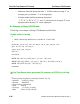
Table Of Contents
- Bookcase
- TABLE OF CONTENTS
- LIST OF FIGURES
- LIST OF TABLES
- About This Manual
- Chapter 1 Introduction
- Chapter 2 Command Dictionary
- Command Summary
- Command Descriptions
- Abort Interrupted Process
- Add Ambiguous Paths
- Add Atpg Constraints
- Add Atpg Functions
- Add Capture Handling
- Add Cell Constraints
- Add Cell Library
- Add Clocks
- Add Cone Blocks
- Add Control Points
- Add Display Instances
- Add Display Loop
- Add Display Path
- Add Display Scanpath
- Add Faults
- Add Iddq Constraints
- Add Initial States
- Add LFSR Connections
- Add LFSR Taps
- Add LFSRs
- Add Lists
- Add Mos Direction
- Add Net Property
- Add Nofaults
- Add Nonscan Handling
- Add Notest Points
- Add Observe Points
- Add Output Masks
- Add Pin Constraints
- Add Pin Equivalences
- Add Pin Strobes
- Add Primary Inputs
- Add Primary Outputs
- Add Random Weights
- Add Read Controls
- Add Scan Chains
- Add Scan Groups
- Add Scan Instances
- Add Scan Models
- Add Slow Pad
- Add Tied Signals
- Add Write Controls
- Analyze Atpg Constraints
- Analyze Bus
- Analyze Control
- Analyze Control Signals
- Analyze Drc Violation
- Analyze Fault
- Analyze Observe
- Analyze Race
- Analyze Restrictions
- Close Schematic Viewer
- Compress Patterns
- Create Initialization Patterns
- Create Patterns
- Delete Atpg Constraints
- Delete Atpg Functions
- Delete Capture Handling
- Delete Cell Constraints
- Delete Clocks
- Delete Cone Blocks
- Delete Control Points
- Delete Display Instances
- Delete Faults
- Delete Iddq Constraints
- Delete Initial States
- Delete LFSR Connections
- Delete LFSR Taps
- Delete LFSRs
- Delete Lists
- Delete Mos Direction
- Delete Net Property
- Delete Nofaults
- Delete Nonscan Handling
- Delete Notest Points
- Delete Observe Points
- Delete Output Masks
- Delete Paths
- Delete Pin Constraints
- Delete Pin Equivalences
- Delete Pin Strobes
- Delete Primary Inputs
- Delete Primary Outputs
- Delete Random Weights
- Delete Read Controls
- Delete Scan Chains
- Delete Scan Groups
- Delete Scan Instances
- Delete Scan Models
- Delete Slow Pad
- Delete Tied Signals
- Delete Write Controls
- Diagnose Failures
- Dofile
- Exit
- Extract Subckts
- Flatten Model
- Flatten Subckt
- Help
- Insert Testability
- Load Faults
- Load Paths
- Macrotest
- Mark
- Open Schematic Viewer
- Read Modelfile
- Read Procfile
- Read Subckts Library
- Redo Display
- Report Aborted Faults
- Report Atpg Constraints
- Report Atpg Functions
- Report AU Faults
- Report Bus Data
- Report Capture Handling
- Report Cell Constraints
- Report Clocks
- Report Cone Blocks
- Report Control Data
- Report Control Points
- Report Core Memory
- Report Display Instances
- Report Drc Rules
- Report Environment
- Report Failures
- Report Faults
- Report Feedback Paths
- Report Flatten Rules
- Report Gates
- Report Hosts
- Report Id Stamp
- Report Iddq Constraints
- Report Initial States
- Report LFSR Connections
- Report LFSRs
- Report Lists
- Report Loops
- Report Mos Direction
- Report Net Properties
- Report Nofaults
- Report Nonscan Cells
- Report Nonscan Handling
- Report Notest Points
- Report Observe Data
- Report Observe Points
- Report Output Masks
- Report Paths
- Report Pin Constraints
- Report Pin Equivalences
- Report Pin Strobes
- Report Primary Inputs
- Report Primary Outputs
- Report Procedure
- Report Pulse Generators
- Report Random Weights
- Report Read Controls
- Report Scan Cells
- Report Scan Chains
- Report Scan Groups
- Report Scan Instances
- Report Scan Models
- Report Seq_transparent Procedures
- Report Slow Pads
- Report Statistics
- Report Test Stimulus
- Report Testability Data
- Report Tied Signals
- Report Timeplate
- Report Version Data
- Report Write Controls
- Reset Au Faults
- Reset State
- Resume Interrupted Process
- Run
- Save Flattened Model
- Save Patterns
- Save Schematic
- Select Iddq Patterns
- Select Object
- Set Abort Limit
- Set Atpg Compression
- Set Atpg Limits
- Set Atpg Window
- Set AU Analysis
- Set Bist Initialization
- Set Bus Handling
- Set Bus Simulation
- Set Capture Clock
- Set Capture Handling
- Set Capture Limit
- Set Checkpoint
- Set Clock Restriction
- Set Clock_off Simulation
- Set Clockpo Patterns
- Set Contention Check
- Set Control Threshold
- Set Decision Order
- Set Dofile Abort
- Set Drc Handling
- Set Driver Restriction
- Set Fails Report
- Set Fault Mode
- Set Fault Sampling
- Set Fault Type
- Set Flatten Handling
- Set Gate Level
- Set Gate Report
- Set Hypertrophic Limit
- Set Iddq Checks
- Set Iddq Strobe
- Set Instancename Visibility
- Set Instruction Atpg
- Set Internal Fault
- Set Internal Name
- Set Interrupt Handling
- Set IO Mask
- Set Learn Report
- Set List File
- Set Logfile Handling
- Set Loop Handling
- Set Multiple Load
- Set Net Dominance
- Set Net Resolution
- Set Nonscan Model
- Set Number Shifts
- Set Observation Point
- Set Observe Threshold
- Set Output Comparison
- Set Output Mask
- Set Pathdelay Holdpi
- Set Pattern Source
- Set Possible Credit
- Set Procedure Cycle_checking
- Set Pulse Generators
- Set Race Data
- Set Rail Strength
- Set Ram Initialization
- Set Ram Test
- Set Random Atpg
- Set Random Clocks
- Set Random Patterns
- Set Random Weights
- Set Redundancy Identification
- Set Schematic Display
- Set Screen Display
- Set Self Initialization
- Set Sensitization Checking
- Set Sequential Learning
- Set Shadow Check
- Set Simulation Mode
- Set Skewed Load
- Set Split Capture_cycle
- Set Stability Check
- Set Static Learning
- Set Stg Extraction
- Set System Mode
- Set Test Cycle
- Set Trace Report
- Set Transition Holdpi
- Set Unused Net
- Set Workspace Size
- Set Xclock Handling
- Set Z Handling
- Set Zhold Behavior
- Set Zoom Factor
- Setup Checkpoint
- Setup LFSRs
- Setup Pin Constraints
- Setup Pin Strobes
- Setup Tied Signals
- Step
- System
- Undo Display
- Unmark
- Unselect Object
- Update Implication Detections
- View
- View Area
- Write Core Memory
- Write Environment
- Write Failures
- Write Faults
- Write Initial States
- Write Library_verification Setup
- Write Loops
- Write Modelfile
- Write Netlist
- Write Paths
- Write Primary Inputs
- Write Primary Outputs
- Write Procfile
- Write Statistics
- Write Timeplate
- Zoom In
- Zoom Out
- Chapter 3 Shell Commands
- Chapter 4 Test Pattern File Formats
- Chapter 5 Distributed FlexTest
- Appendix A Timing Command Dictionary
- Appendix B FlexTest WDB Translation Support
- INDEX
- Send us feedback

Test Pattern File Formats FlexTest Test Pattern File Format
FastScan and FlexTest Reference Manual, V8.6_4
4-27
VCD Support Using VCD Plus
FlexTest accepts existing Verilog or VHDL functional patterns through its VCD
(Value Change Dump) Plus files which can be generated during simulation. This
functionality is useful because FlexTest can use existing functional patterns to get
some initial fault coverage, and then perform ATPG on the remaining faults. This
can result in smaller test pattern sets and shorter run times. Also due to that fact
that the FlexTest fault simulation engine doesn’t consider timing, FlexTest fault
simulation should be faster than other fault simulators.
This feature mainly contains two tasks:
• Parsing a VCD Plus file.
• Converting the event based patterns in the VCD file to cycle based vectors
stored in FlexTest internal pattern data structure which can be used by the
cycle based FlexTest fault simulation engine to perform fault simulation.
The VCD Plus format that is supported is the LSI Logic’s extended VCD format.
Comparing with the standard VCD format, the extended VCD format provides
sufficient simulation information on bidirectional signals -- driving direction,
driving strength and collision detection. For more detailed information about LSI
Logic’s extended VCD format and the methods of generating it from various
simulators, contact LSI Logic and the respective EDA vendor.
To create a VCD Plus file for a VHDL or Verilog design from ModelSim EE/Plus
(using version 5.1e or later), use the following ModelSim commands:
vcd file filename.vcd -dumpports
vcd add -r