
User Manual


9
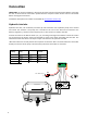
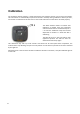
Electromechanical trim tabs
Connect the starboard actuator to terminals 5 and 6 and the port actuator to terminals 3 and 4,
according to the figure that follows. Verify the connection later on and change it if necessary.
*Lenco’s electronic control panels usually have a separate control box. ACS is connected after the
control box directly to the wires of the cylinders. The old control panel and control box are removed.
ACS
marking
Lenco* Lectrotab Ultraflex
Bennett
Bolt
3 Black (port) White (port) Black (port) Yellow (port)
4 White (port) Black (port) White (port) Blue (port)
5 Black (stbd) White (stbd) Black (stbd) Yellow (stbd)
6 White (stbd) Black (stbd) White (stbd) Blue (stbd)
10...30V dc (+)
(-)
20A
1 2 3 4 5 6 7
3/4 5/6
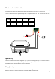
Ignition key
Terminal 7 may be connected to the ignition key run position. If the ignition key is connected, retraction
will take place when switching off the engine. Without the ignition key connection, retraction will take
place after a delay when the boat has come off the plane.
Supply voltage
Connect a red wire to the boat’s main circuit breaker through a fuse. Connect a black wire to the
battery's negative (-) terminal. Minimum 2.5 mm2 (14 AWG) is recommended.