FullView Direct Vent Gas Fireplace Insert Heater With Premium Texture Fiber Logs Combustion System MODEL #E-FV33I ECHO SERIES INSTALLATION & OPERATING INSTRUCTIONS DOCUMENT NO. E-FV33i-1011 WARNING: If the information in this manual is not followed exactly, a fire or explosion may result causing property damage, personal injury or loss of life. Do not store or use gasoline or other flammable vapors and liquids in the vicinity of this or any other appliance. WHAT TO DO IF YOU SMELL GAS Open windows.
SAFETY AND WARNING INFORMATION FOR YOUR SAFETY A qualified installer, service agency, or the gas supplier must perform installation and service. WARNING: Improper installation, adjustment, alteration, service or maintenance can cause injury or property damage. Refer to this manual. For assistance or additional information consult a qualified installer, service agency or the gas supplier. Do not store or use gasoline or other flammable vapors and liquids in the vicinity of this or any other appliance.
Due to high temperature, the appliance should be LOCATED out of traffic areas and away from furniture and draperies. En raison des températures élevées, l’appareil devrait être installé dans un endroit où il y a peu de circulation et loin du mobilier et des tentures. Clothing or flammable material SHOULD NOT BE PLACED on or near the appliance. On ne devrait pas placer de vêtements ni d’autres matières inflammables sur l’appareil ni à proximité.
E-FV33i FEATURES - QUICK REFERENCE INFORMATION EXTERNAL DIMENSIONS: 30-3/8” Wide X 18-3/8” High X 15-3/4” Deep 2 2 GLASS SIZE: NeoCeram Glass with non-reflective coating. Visible Glass measures 398 in . Actual Glass size is 468 in . MINIMUM FIREPLACE DIMENSIONS REQUIREMENT: 30-1/2 Wide X 18-3/8” High X 15-3/4” Deep MANTEL ALLOWANCE: 8” Deep Mantel at 12” Above Top Convection Opening Or 30-1/16” Above Floor Level Of This Appliance. Use the Approved Mantel Profile Chart.
TABLE OF CONTENTS SAFETY AND WARNING INFORMATION ...................................................................................................................................... 1 E-FV33I FEATURES - QUICK REFERENCE INFORMATION ........................................................................................................ 3 INITIAL STARTUP ADVICE .....................................................................................................................................................
GLASS FRAME ASSEMBLY REPAIR AND REPLACEMENT ...................................................................................................... 54 MENDOTA WARRANTY QUALIFICATION & SERVICE REFERENCE FORM .................................................................................. 55 MENDOTA EXTENDED LIFETIME PROTECTION AND LIMITED WARRANTY .....................................................................
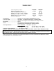
SPECIFICATIONS MODEL E-FV-33i Input rating (Btu/hr) 0-610 m Minimum input (Btu/hr) 0-610 m Orifice size (DMS) 0-610 m (front/rear) Manifold pressure (in. w.c./kPa) > High Fire Manifold pressure (in. w.c./kPa) >Low Fire Minimum inlet pressure (in. w.c./kPa) Air shutter settings (in) Natural Gas 31,000 21,000 21,000 49/45 3.5/0.87 1.7/0.42 5.0/1.24 1/16” Propane Gas 31,000 00 25,000 25 3 3 /64”/ /64” 10.0/2.49 6.3/1.57 11.0/2.74 ¼” EFFICIENCIES ..................................EXCEEDS D.O.E.
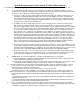
Specific Requirements for the Common Wealth of Massachusetts The information in this section applies to all installations performed in the Common Wealth of Massachusetts only. a) For all side wall horizontally vented gas fueled equipment installed in every dwelling, building or structure used in whole or in part for residential purposes and where the side wall exhaust vent termination is less than seven (7) feet above grade, the following requirements shall be satisfied: 1.
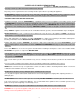
SAFETY AND WARNING INFORMATION READ and UNDERSTAND all instructions carefully before starting the appliance. FAILURE TO FOLLOW these instructions may result in a possible fire hazard and will void the warranty. Any safety screen or guard removed for servicing must be replaced before operating this appliance. DO NOT USE this appliance if any part has been under water.
CONGRATULATIONS You are the owner of a world-class heat producing gas direct vent sealed combustion fireplace. This elegant, highly efficient Fireplace will be a constant source of comfort and fascination. It will be the focal point of beauty and interest in your home. The Mendota Gas Fireplace is a true heating appliance incorporating the traditional aesthetics of fireplace fire viewing with the controllability and fuel efficiency of a home gas furnace.
GENERAL INFORMATION Your Mendota Gas Fireplace Insert has a state-of-the-art direct vent, sealed combustion system. This advanced, highly efficient system brings in outside air for combustion, has a separate exhaust vent and efficiently heats and recirculates room air. The Mendota system maintains high air quality, maximizes efficiency and assures proper operation. SAFETY AND STRUCTURAL CONCERNS: The E-FV33i Fireplace Insert must be installed and serviced by a Mendota approved serviceperson.
LOCATIONS OF FUNCTIONAL COMPONENTS STANDING PILOT LIGHT SWITCH REMOTE RECEIVER ACCENT LIGHT HOUSING SECONDARY AIR INTAKE DAMPER ADJUSTMENT FAN CONTROL MODULE RIGHT BLOWER ACCENT LIGHT DIMMER SWITCH PRIMARY AIR INTAKE VELOCITY ADJUSTMENT IS LOCATED HERE! LEFT BLOWER REAR BURNER SOLENOID VALVE RECEIVER MAIN GAS VALVE IPI CONTROL MODULE 11 SLIDING VENT ADAPTER ACCENT LIGHT DIMMER SWITCH
E-FV33i OVERALL DIMENSIONS 30 3/8 MINMUM FIREPLACE WIDTH REQUIRED AT FRONT OPENING 22 3/16 MINIMUM FIREPLACE WIDTH REQUIRED AT REAR WALL 9 5/8 12 7/8 1 7/8 15 3/4 MINIMUM FIREPLACE DEPTH REQUIRED SURROUND/FACEPLATE DEPTH -B29 27 5/8 VISIBLE GLASS SIZE = 398 SQ. IN. ACTUAL GLASS SIZE = 468 SQ. IN. -A- 15 3/8 30 1/8 17 3/8 25 7/8 1 7/8 15 3/4 5 1/2 Minimum Fireplace 7 7/8 Depth Required 1.
MENDOTA E-FV33i GAS DIRECT VENT FIREPLACE INSERT SPECIFICATIONS & CLEARANCES Minimum Fireplace Opening Required 30-3/8” wide X 18-3/8” high X 15 3/4” Deep E-FV33i Faceplate Dimensions A 30 3/8 No Trim Is available For E-FV33I 22 3/16 Inches 24 27 31 B mm. 610 686 788 Inches 36 40 44 15 3/4 35 211 16 16 15 2 11 16 16 16" MIN. FROM GLASS FRAME EDGE TO PERPENDICULAR SIDE WALL 12 11 10 9 8 7 6 5 4 3 2 1 0 DISTANCE TO MANTEL (IN.
INSTALLATION INSTRUCTIONS CAUTION: Each installation must conform to all local, state and national codes. Refer to the national fuel gas code and local zoning and code authorities for details on installation requirements. The Mendota Inserts must be vented to the outside in accordance with the latest edition of the National Fuel Gas Code. In the absence of local codes, the installation must conform with National Fuel Gas Code ANSI Z223.
FLUE VENTING The E-FV33i Insert must be vented vertically to the outside and must use the Mendota Co-Linear flexible ducting system. The minimum vertical vent length required is 10 feet. The maximum allowed vertical vent length is 70 feet. In the USA, the air-intake pipe may be run past the damper into the chimney and terminated with an open end 2 feet past the damper mechanism.
Chimney Flashing and cap (See FIGURE BELOW) The vent kits include a trim-able flashing. Measure, trim and shape flashing to fit the existing flue liner. This flashing prevents water and small animals from entering area between the chimney liner and flue liner. Plan for 1” to 1-1/2” (25 mm to 38 mm) overlap on each side. Center the flashing and mark it about 3" (75 mm) larger in each dimension than the existing chimney. Trim the notch with snips and bend edges with hand seaming tool, metal break or pliers.
14. Remove the Vent Adapter by removing two 5/16” Hex Bolts and sliding Vent Adapter towards rear of Insert. 3-7/8" EXHAUST STUB 2-7/8" AIR INTAKE STUB 15. Tightly secure 3” and 4” flex vents with clamps provided. Seal vent cap/flashing to top of chimney with weatherproof sealer. Seal areas between flex pipes and existing chimney, at damper area, with unfaced fiberglass insulation. 16.
18. You are now ready to hook up the Insert to gas supply. Be sure gas plumbing instructions and all state and local codes have been carefully followed. Be sure all items on Installation Check-Off List have been completed. NOTE: AGA APPROVED FLEX LINES ARE APPROVED FOR USE WITH MENDOTA INSERTS. 19. Carefully slide the Insert into place in the fireplace opening. At this time, check that Insert is level and plumb with the fireplace opening and positioned in the middle of the opening.
RAISED HEARTH SPECIFICATIONS BOTTOM EDGE OF GLASS WINDOW In most installations, a 16" non-combustible protector is required in front of the unit’s glass door surface on the floor or raised hearth. This protection can be any non-combustible material such as 24-gauge sheet metal, tile, brick, concrete board, etc. Please note that the required 16” clearance starts at the front face of the glass door.
GAS SUPPLY REQUIREMENTS NOTE: IF INSERT IS TO BE OPERATED WITH LP GAS, SEE PAGE 34 BEFORE PROCEEDING. CORRECT GAS PRESSURE AND PROPER GAS SUPPLY LINE SIZING IS IMPERATIVE TO THE SUCCESSFUL PERFORMANCE OF YOUR ENDOTA GAS FIREPLACE INSERT. BE SURE THE GAS SUPPLIER OR PLUMBER CAREFULLY CHECKS FOR CORRECT GAS PRESSURE AND GAS LINE SIZING WHEN INSTALLING THE FIREPLACE INSERT. IT IS CRITICAL TO CAREFULLY CHECK FOR GAS LEAKS WHEN HOOKING UP THE FIREPLACE INSERT -- CHECK WITH SOAP & WATER SOLUTION.
GAS PRESSURE REQUIREMENTS One major cause of operating problems with gas appliances can be improper gas pressure! Such problems as changes in flame color or configuration, gas pilot or burner outages, intermittent operation , changes in heat output, excessive burner noise, etc. are nearly always the result of changes in gas pressure or improper gas pressure at the time of the installation.
HIGH ALTITUDE INSTALLATIONS For installations from 610-1370 meters (2000-4500 ft.) the orifice sizes (DMS) for natural gas are #46R/#49F and for propane gas is #56R/#3/64”F. See data plate for additional information. For high altitude installations consult the local gas distributor or the authority having jurisdiction for proper rating methods.
INSTALLATION CHECK OFF LIST The following check list must be completed prior to initial lighting of the Fireplace Insert, or manufacturer's warranty and liabilities will be voided: Venting system must be installed by a Mendota approved person according to Figure 3, Pg. 15 with clamps securely in place and all joints leak proof. Electrical supply and gas supply must be properly installed and must conform to National and Local Codes. Check that correct fuel supply is connected to appliance.
DOOR REMOVAL AND REPLACEMENT CAUTION: Do not operate the appliance with glass removed, cracked or broken. Replacement of the glass should be done by a licensed or qualified service person. Glass latch tool #HA-57-00743 is supplied with the unit. To Unlatch Glass Frame Latches: 1. Insert Glass Latch Tool into hole in latch (two latches exist at top of glass frame). 2. Pull Glass Latch Tool outward about 3/8”. 3. Rotate Glass Latch Tool 90 degrees. 4. Release Glass Latch Tool. 5. Remove Glass Latch Tool. 1.
E-FV33i LOG SET INSTALLATION INSTRUCTIONS FOLLOW EACH STEP DEPICTED IN THE DIAGRAMS, BELOW, TO INSTALL THE LOG SET. CAUTION: LOGS ARE FRAGILE, HANDLE LOG PIECES WITH CARE. Carefully unpack 9-piece log set and bag of coals. NOTE: Logs are very fragile, handle with care. Coals must not block pilot or burner flame! Placement of coals has a big effect on front burner flame appearance and "glow" of coals. More coals = less yellow flame and more glow. Fewer coals = more yellow flame and less "glow".
PLACE LOG #1 (REAR LOG) ON REAR SHELF BEHIND REAR BURNER. SLIDE LOG TO RIGHT UNTIL LOG TOUCHES RIGHT SIDE BRICK PANEL. PUSH LOG BACK SO IT TOUCHES REAR BRICK PANEL. THIS LOG IS RECOMMENDED TO BE PUSHED TO THE FAR RIGHT SIDE.
LOG #2 27 LOG# 1 LOG #2 PLACE LOG #2 BETWEEN THE TWO BURNERS AND SLIDE TO THE RIGHT UNTIL THE CURVATURE IN THE FRONT BURNER CONTACTS THE CURVATURE ON THE RIGHT FRONT TIP OF LOG #2. PUSH LOG #2 DOWN TO INDENT THE BOTTOM WITH THE TWO BURNER MOUNTING SCREW HEADS. LOG #2 MUST NOT ROCK ON TOP OF THE SCREW HEADS. LOG #2 MUST BE STABLE STABLE. LOG #2 (MID EMBER BED) SITS BETWEEN REAR AND FRONT BURNER, FLAT DOWN ON THE SURFACE OF THE BURNER AIRBOX.
LOG# 3 BURNER LOG# 3 LOG# 3 LOG# 1 LOG #2 LOG #3 MUST LEAVE CLEARANCE FOR THE REAR BURNER PORTS. SOME ROTATIONAL FLEXIBILITY IS ALLOWED FOR THE REAR END OF THIS LOG TO ROTATE TOWARDS LOG #2. HOWEVER, LOG #3 SHALL NEVER SIT ON TOP OF THE REAR BURNER PORTS. DOING SO WILL LEAD TO SOOT CREATION. PLACE LOG #3 (LEFT LOG) ON TOP OF THE RECTANGLE AIR SHUTTER BOX ON THE LEFT SIDE. LOG #3 HAS A RECTANGULAR NOTCH ON ITS BOTTOM SIDE THAT ALLOWS THE LOG TO SIT SQUARELY ON TO OF THE BOX.
LOG #4 29 REAR TIP OF LOG #4 MUST SIT ON TOP OF LOG #2, HERE. LOG #2 LOG# 4 LOG# 1 LOG #4 (RIGHT LOG) HAS A HOLE FOR THE PIN ON LOG #2. INSERT PIN IN LOG #2 INTO HOLE IN LOG #4. SET RIGHT END OF LOG #4 ON TOP OF THE FIRST GRATE BAR ON THE FAR RIGHT SIDE. SOME ROTATIONAL FLEXIBILITY IS ALLOWED TO LOG #4 AROUND THE PIN AND HOLE. HOWEVER, DO NOT ROTATE REAR END OF LOG OUTWARD. ROTATE INWARD ONLY IF DESIRED.
LOG# 3 LOG# 5 PUSH LOG #5 BACK SO ITS REAR END TOUCHES THE REAR BRICK PANEL. THE V‐NOTCH BETWEEN THE TWO BRANCHES MUST SIT DIRECTLY ON TOP OF THE REAR BURNER’S LEFT SIDE PORTS AND MUST ALLOW THE FLAMES TO RISE INTO THE V‐NOTCH IN THIS LOG. LOG #5 (LEFT TOP LOG) SITS ON THE LEFT SHOULDER OF LOG #1 AND ITS TWO BRANCHES SIT ON TOP OF LOG #2 AND LOG #3. LOG #5 HAS A HOLE THAT ALIGNS WITH THE LEFT SIDE PIN ON LOG #1.
LOG# 1 LOG #2 31 LOG# 4 LOG# 6 LOG# 4 LOG# 6 SOME ROTATIONAL FLEXIBILITY IS ALLOWED FOR LOG #6. THE POSITION OF LOG #4 WILL LIMIT THE ROTATION #6 OF LOG #6. PLACE LOG #6 ON TOP OF LOG #1’S PIN. THE OTHER END OF LOG #6 SITS ON TOP OF LOG #2 AS SHOWN, BELOW. LOG #6 (RIGHT TOP LOG) SITS ON TOP OF LOG #1 USING THE PIN THAT IS ON THE RIGHT SIDE OF LOG #1. LOG #6 HAS A HOLE IN ITS BACK‐SIDE TO MATE WITH THIS PIN.
LOG# 4 32 LOG# 7 LOG# 7 LOG# 4 LOG #7 REST ON TOP OF THE FRONT BURNER’S REAR VISIBLE EDGE AND ON TOP OF LOG #4. THIS LOG IS DESIGNED TO HIDE THE PILOT LIGHT. PLACE THIS LOG SO IT PROVIDES CLEARANCE TO ALL BURNER FLAMES AND PILOT FLAMES, YET POSITIONED TO HIDE THE PILOT FLAMES.
LOG# 8 LOG# 2 LOG# 2 33 2ND BAR LOG# 8 LOG# 2 DO NOT PINCH FRONT BURNER PORTS WITH LOG #8. ATTEMPT TO POSITION LOG #8 AS SHOWN HERE FOR THE BEST GLOW EFFECT AND REALISTIC LOOK. PLACE LOG #8 ( LEFT FRONT TWIG) IN THE POSTION SHOWN HERE. LOG #8 SITS ON TOP OF LOG #2 AND RESTS AGAINST THE GRATE BAR (2ND FROM LEFT).
USING A TOOTH BRUSH, BRUSH INSWOOL (GLOWING EMBERS) RANDOMLY OVER LOG #2, THE COALS AND IN AREAS WHERE YOU WISH TO SEE GLOWING EMBER EFFECTS. SCATTER SMALL COALS ON THE FLOOR AND BETWEEN THE LOG GRATE’S HORIZONTAL BAR AND THE FRONT BURNER. A FEW COALS MAY SIT ON TOP OF THE FRONT BURNER TUBE BUT AVOID PLACING TOO MANY COALS ON TOP OF THE FRONT BURNER PORTS. LOG #9 (RIGHT FRONT CHUNK) IS TO BE PLACED AT A SEVERE ANGLE AGAINST THE HORIZONTAL GRATE BAR AND FLOATING OVER THE FRONT BURNER PORTS.
35 COMPLETED LOG SET ASSEMBLY
REMOTE TRANSMITTER OPERATING INSTRUCTIONS TO TURN ON THE APPLIANCE: 1. 2. Press the ON/OFF button. The transmitter display will show all active icons on the screen. Select the Thermostat Mode by pressing the Thermostat Key: OFF (meaning Manual Mode), ON (meaning normal Thermostat) or Smart (meaning Smart Mode). a. In OFF (Manual Mode), the appliance will ignite and start on HI. b. In ON (Normal Thermostat Mode), the appliance will only ignite if the Set Temperature is greater than the Room Temperature. c.
BEFORE YOU BEGIN Read this entire manual before you use your new fireplace (especially the section “Safety Precautions” on page 7). Failure to follow the instructions may result in property damage, bodily injury, or even death. Remote Control Transmitter Functions NOTE: The Receiver will “beep” once every time a Remote Transmitter Key is pressed, signaling that the command has been received. Identify the four function buttons on the Remote Transmitter: 1. ON/OFF KEY: This button turns the system ON or OFF.
MANUAL BYPASS OF THE REMOTE SYSTEM If the remote transmitter is misplaced or lost, the appliance can be turned on manually by sliding the three position slider switch on the receiver to the ON position. This will bypass the remote control feature of the system and the appliance’s main burner will turn on. \ To turn off the appliance, if the remote control is misplaced or lost, slide the three position slider switch on the receiver to the OFF Position. TEMPERATURE INDICATOR (oF or oC) 1.
“FIRST TIME” PILOT LIGHTING INSTRUCTIONS IMPORTANT: Be sure all items on "INSTALLATION CHECK OFF LIST" in the Installation Manual have been completed! CAUTION: If the pilot goes out, be sure to wait a minimum of five minutes before attempting to relight the pilot. 1. Make certain that any manual gas supply shut-off valves located upstream of fireplace are open and the receiver and the remote control transmitter are in the "OFF" position.
INITIALIZING THE REMOTE CONTROL SYSTEM (Synchronizing Receiver and Transmitter) BLUE LCD DISPLAY WALL RECEIVER G 3-POSITION SLIDER SWITCH PR 1. Place 3-position slider switch in Receiver in the “Remote” position. 2. Locate “PRG” key on Receiver Face. Use the tip of a pen/pencil or a wire clip to push the PRG button. The receiver will beep 3 times indicating that it is ready to synchronize with a Remote Transmitter. 3. Push the “ON” key on the Remote Transmitter.
E-FV33i GAS IGNITION SYSTEM WIRING DIAGRAM 41
MAINTENANCE 1. ANNUAL MAINTENANCE OF MENDOTA UNITS IS REQUIRED. The following procedures must be performed each year by a Mendota approved service person. NOTE: Any adjustments to burner, pilot or logs must be done by a qualified Mendota service person. A. Clean all lint and dust build-up around the control. Inspect the condition of any wiring under the burner for melting or damage. B. Remove logs & coals and clean away any foreign matter (lint, Carbon, etc.) on the burner and logs.
NATURAL TO LP GAS CONVERSION INSTRUCTIONS This conversion kit shall be installed by a qualified service agency in accordance with the manufacturer’s instructions and all applicable codes and requirements of the authority having jurisdiction. If the information in these instructions is not followed exactly, a fire, explosion or production of carbon monoxide may result causing property damage, personal injury or loss of life. The qualified service agency is responsible for the proper installation of this kit.
5. 6. 7. Using a ½” deep well socket wrench, remove Front and Rear Orifices. Thread a new 3/64” drilled orifice to both Front and Rear Orifice mounting brass fittings. Tighten down orifices. Remove the left-side access panel mounted to the left outer skin and lay down gently without disconnecting any wires of internal components. DETAIL C REAR ORIFICE REAR BURNER PILOT LIGHT HOOD FRONT ORIFICE FRONT BURNER DETAIL D 8. Install pilot orifice thimble ##977.168 see Figure below for location.
11. Before reinstalling burners, loosen the screw that secures the rotary air shutter on the Front Burner. Rotate the air shutter open to ¼” minimum. 12. Install both rear and front burners in their original locations and positions and secure down using screws you removed earlier. LOOSEN SCREW ROTATE SHUTTER OPEN -1/4" MINIMUM- FRONT BURNER SHUTTER ADJUSTMENT 13.
You must remove the left side Valve Access Panel to replace the pressure regulator. 1. Remove the left-side access panel mounted to the left outer skin and lay down gently without disconnecting any wires of internal components. WARNING: DO NOT FORCE. EXCESSIVE FORCE MAY DAMAGE INTERNAL WIRING COMPONENTS! REMOVE (4) SCREWS "ONLY" THAT HOLD LEFT SIDE COVER. 2. See diagrams on this page and identify the Pressure Regulator on the Valve Body. 3.
LP PRESSURE REGULATOR CONVERSION INSTRUCTIONS WARNING: Failure to position the parts in accordance with these diagrams or failure to use only parts specifically approved with this appliance may result in property damage or personal injury.” AVERTISSEMENT. Risque de dommages ou de blessures si les pièces ne sont pas installées conformément à ces schémas et ou si des pièces autres que celles spécifiquement approuvées avec cet appareil sont utilisées.
LP GAS PRESSURE REQUIREMENTS Inlet and manifold gas pressure checking taps are located on gas valve. These ports are only accessible from the outer left side of the fireplace. A qualified installer shall take pressure measurements at these ports to verify and set the correct gas pressures during the LP Kit installation and before facia materials are installed over the front of this fireplace.
CHECKING FOR NORMAL BURNER (S) IGNITION CHARACTERISTICS Once the conversion to LPG and all the above steps have been completed, light the main burners. Turn Gas Dial counterclockwise to "ON" then set Thermostat or push Main Burner ON/OFF switch to turn on burners. Main burner should now light IMMEDIATELY and flame should not "lift" off burner.
CUSTOMER INFORMATION AND TROUBLE-SHOOTING MAXIMUM ALLOWABLE SURFACE TEMPERATURE Mendota Inserts/Fireplaces comply with UL Standards for maximum surface temperatures on exposed combustible surfaces adjacent to the Insert. The Maximum allowable surface temperature is 117° F. over ambient (room) temperature. Thus, if a room is 70° – 80° the exposed combustible surfaces immediately surrounding the Insert can have a surface temperature as high as 187° F. – 200° F. (Too hot to touch).
BURNER FLAMES ADJUSTMENT- AIR INTAKE DAMPER CONTROLS This appliance is equipped with two Air Intake Adjustment Damper Controls: PRIMARY DAMPER and SECONDARY DAMPER. It is important to understand the functions of the two dampers prior to adjusting them. VENT LENGTH DAMPER POSITION 10-20 FEET 45o OPEN PRIMARY AIR INTAKE DAMPER: The PRIMARY AIR INTAKE 30 FEET 60o CLOSED DAMPER is located on the top of the Air Intake Pipe attachment Stub. This Damper is factory set at 45 degrees OPEN.
BURNERS AIR SHUTTER CONTROLS During the initial installation, the Front Burner Rotary Manual Air shutter opening should be checked to make certain that the shutter is set correctly at 1/16" open for natural gas and 1/4" minimum open for L.P. gas. NOTE: For altitudes above 5,000 ft., increase to 1/8” Open for NG and 3/8” Open for LPG. Be sure burner and logs are properly installed.
GAS VALVE TRAIN ASSEMBLY REPLACEMENT PARTS LIST E-FV33i VALVE ASSEMBLY COMPONENTS LIST KEY# 1 3 4 5 6 7 8 9 11 13 14 15 16 17 QTY 1 1 1 2 1 1 1 1 1 1 1 1 1 1 Part Number 05-02-00344 05-04-00050 05-04-00059 50-06-00109 55-02-00087 55-02-00088 60-01-00257 60-05-00055 65-07-00010 65-07-00024 65-07-00744 65-14-00045 65-14-00049 HA-57-00714 Description 885 PROFLAME SIT VALVE PILOT ASSY, SIT PILOT TUBE 30", SIT, 2.182.
GLASS FRAME ASSEMBLY REPAIR AND REPLACEMENT DO NOT substitute other manufacturer's materials or components. DO NOT operate unit with cracked, broken or missing glass. DO NOT abuse the glass door by striking the glass, slamming the door shut, etc WARNING Use only authorized parts and materials obtained from Johnson Gas Appliance Company when replacing defective or damaged glass. WARNING Do not operate this appliance with the glass removed, cracked or broken.
MENDOTA WARRANTY QUALIFICATION & SERVICE REFERENCE FORM As a part of Mendota's on-going program of customer satisfaction, this Form verifies proper installation and operation. It is important as a reference for future service. It insures long life and trouble-free operation of Mendota fireplaces & stoves and qualifies the owner for Mendota's lifetime limited warranty. Owner should sign Form when completed. Optionally, please register at our website at : WWW.JOHNSONGAS.COM/MENDOTA-REGISTRATION.
THIS PAGE LEFT BLANK, INTENTIONALLY.
TAPE SHUT ---------------------------------------------------------------------------------------------------------------------------------------------- POSTAGE NEEDED JOHNSON GAS APPLIANCE COMPANY 520 E AVENUE N.W.
MENDOTA EXTENDED LIFETIME PROTECTION AND LIMITED WARRANTY MENDOTA GAS FIREPLACE INSERT MODEL: E-FV33i NAT. & L.P. Mendota Division of Johnson Gas Appliance Company, 520 E Avenue N.W. Cedar Rapids, Iowa 52405, extends this Extended Lifetime Protection and Limited Warranty to the original purchaser of a Mendota Gas Fireplace Insert, Serial Number , which is limited and used under normal home conditions. STANDARD WARRANTY: JOHNSON GAS APPLIANCE CO.
Johnson Gas Appliance Company 520 E Avenue N.W. - Cedar Rapids, IA 52405 Website: www.johnsongas.com or www.mendotahearth.