UN UF IN IF SN SF PLUS PLUS PLUS PLUS PLUS PLUS OPERATING INSTRUCTIONS UNIVERSAL OVEN U INCUBATOR I STERILISER S 100% ATMOSAFE. MADE IN GERMANY. www.memmert.com | www.atmosafe.
Manufacturer and customer service Memmert GmbH + Co. KG Willi Memmert Straße 90-96 D-91186 Büchenbach Deutschland Phone: +49 (0)9122 925-0 Fax: +49 (0)9122 14585 E-mail: sales@memmert.com Internet: www.memmert.com Customer service: Service hotline: +49 (0)9171 9792 911 Service fax: +49 (0)9171 9792 979 E-mail: service@memmert.com When contacting customer service, always quote the product serial number on the nameplate (see page 13). Shipping address for repairs: Memmert GmbH + Co.
About this manual About this manual Purpose and target group This manual describes the setup, function, transport, operation and maintenance of universal ovens UNPLUS/UFPLUS, sterilisers SNPLUS/SFPLUS and incubators INPLUS/IFPLUS. It is intended for use by trained personnel of the owner, who have the task of operating and/or maintaining the respective appliance. If you are asked to work on the appliance, read this manual carefully before starting. Familiarise yourself with the safety regulations.
Contents Contents 1. For your Safety 1.1 1.2 1.3 1.4 1.5 1.6 1.7 1.8 Terms and signs used........................................................................................................... 6 Product safety and dangers ................................................................................................ 7 Requirements of the operating personnel .......................................................................... 7 Responsibility of the owner.......................................
Contents 7. Menu mode 7.1 7.2 7.3 7.4 7.5 7.6 7.7 7.8 7.9 Overview ............................................................................................................................ 40 Basic operation in menu mode using the example of language selection....................... 41 Setup.................................................................................................................................. 42 Date and Time .................................................................
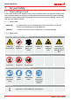
Safety regulations 1. For your Safety 1.1 Terms and signs used In this manual and on the appliance itself, certain common terms and signs are used to warn you of possible dangers or to give you hints that are important in avoiding injury or damage. Observe and follow these hints and regulations to avoid accidents and damage. These terms and signs are explained below. 1.1.
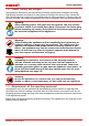
Safety regulations 1.2 Product safety and dangers The appliances described in this manual are technically sophisticated, manufactured using high-quality materials and subject to many hours of testing in the factory. They contain the latest technology and comply with recognised technical safety regulations. However, there are still risks involved, even when the appliances are used as intended. These are described below. Warning! After removing covers, live parts may be exposed.
Safety regulations 1.
Safety regulations 1.6 Changes and alterations No unauthorised changes or alterations may be made to the appliance. No parts may be added or inserted which have not been approved by the manufacturer. Unauthorised modifications or changes result in the CE declaration of conformity losing its validity and the appliance must no longer be operated.
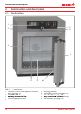
Construction and description 2. Construction and description 2.1 Construction 1 9 8 2 1 3 7 4 5 Abb.
Construction and description 2.2 Function Appliances of the UNPLUS, SNPLUS and INPLUS type series feature natural circulation (convection). For the UFPLUS, SFPLUS and IFPLUS type series, air is circulated by a fan at the working chamber rear panel (Abb. 3, No. 1). It increases the air flow and provides stronger horizontal forced air circulation than natural convection. In both the convection and fan ventilated appliances, supply air (2) is preheated in a pre-heating chamber (3).
Construction and description 2.5 Connections and interfaces 2.5.1 Electrical connection This appliance is intended for operation on an electrical power system with a system impedance Zmax of a maximum of 0.292 ohm at the point of transfer (service line). The operator must ensure that the appliance is operated only on an electrical power system that meets these requirements. If necessary, you can ask your local energy supply company what the system impedance is.
Construction and description 2.6 Designation (nameplate) The nameplate (Abb. 6) provides information about the appliance model, manufacturer and technical data. It is attached to the front of the appliance, on the right side behind the door (see page 10). 1 2 3 Typ: UN 260 plus F.-Nr.: 0109.0088 230 V ~ 14.8 A 50/60 Hz 3400 W DIN12880-Kl.3.1 Nenntemp.: 300 °C 10 9 8 4 7 5 6 Abb.
UN/UF/SN/SF 3 1 60 80 4 75 – – 5 6,1 9,6 12,2 19,1 640 560 480 400 108 78 1100 1400 2800 2200 745 867 584 110 7,0 9,6 13,9 19,1 745 1107 584 56 640 560 720 400 161 96 1100 1600 3200 2200 160 7,4 9,6 14,8 19,1 740 640 800 500 256 110 1100 1700 3400 2200 824 1186 684 260 450 58002 7,8 13,0 3 x 8,42 8 - 840 1040 720 600 449 170 1500 1800 - 1224 1247 784 8 9 30 120 175 210 300 +20 to +80 °C3 +20 to +300 °C3 +20 to +250 °C3 0.1 K up to 100 °C: 0.1 K, above 100 °C: 0.
Construction and description D 56 B E C A Abb. 7 G F Dimensions (see table on page 14) 2.8 Applied directives and standards ► Directive 2004/108/EC amended (Directive of the council on harmonisation of the laws of the member states on electromagnetic compatibility).
Construction and description 2.10 Ambient conditions ► The appliance may only be used in enclosed rooms and under the following ambient conditions: Ambient temperature +5 ºC to +40 ºC Humidity rh max. 80 %, non-condensing Overvoltage category II Pollution degree 2 Altitude of installation max. 2,000 m above sea level ► The appliance may not be used in areas where there is a risk of explosion. The ambient air must not contain any explosive dusts, gases, vapours or gas-air mixtures.
Delivery, transport and setting up 3. Delivery, transport and setting up 3.1 For your Safety Warning! Because of the heavy weight of the appliance, you could injure yourself if you try to lift it. To carry appliances of the sizes 30 and 55, at least two persons, for appliances of the sizes 75, 110, 160 and 260, four people are needed. Appliances larger than that may not be carried but must be transported with a manual pallet jack or forklift truck.
Delivery, transport and setting up 3.2 Delivery The appliance is packed in cardboard and is delivered on a wooden palette. 3.3 Transport The appliance can be transported in three ways: ► With a forklift truck; move the forks of the truck entirely under the pallet ► On a manual pallet jack ► On its own castors, in case of the corresponding configuration, for which the catch on the (front) castors must be released 3.
Delivery, transport and setting up 3.6 Setting up Warning! Due to its centre of gravity, the appliance can fall over to the front and injure you or other people. Always attach the appliance to a wall with the tilt protection (see page 21). If this cannot be done due to space problems, do not operate the appliance and do not open the door. Contact the Memmert service team (see page 2). 3.6.
Delivery, transport and setting up 3.6.2 Installation options Setting up Comments Suitable for appliance size ... 30 55 75 110 160 260 450 750 Check the load capacity first two appliances maximum; mounting material (feet) provided Separately packaged fastening material is included in the scope of delivery. Observe the assembly instructions provided.
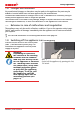
Delivery, transport and setting up 3.6.3 Tilt protection Attach the appliance to a wall with the tilt protection. The tilt protection is included in the delivery. 1. As illustrated, fasten the tilt protection to the rear side of the appliance. ≥ 20 cm 2. Bend the tilt protection upwards by 90 ° in the desired distance to the wall (consider the minimum distance to the wall, see Abb. 9). 3. Drill a hole, insert a plug and screw the tilt protection to a suitable wall.
Putting into operation 4. Putting into operation Caution: The first time the appliance is operated, it must not be left unattended until it has reached the steady state. 4.1 Connecting the appliance Caution: Observe the country-specific regulations when making connections (e.g. in Germany DIN VDE 0100 with residual current circuit breaker). Observe the connection and power ratings (see nameplate and Technical data on page 14). Make sure to establish a safe PE conductor connection.
Operation and control 5. Operation and control Caution: When loading and operating sterilisers of the SNPLUS/SFPLUS type, make sure to observe the special notes provided in chapter Sterilisers SFPLUS/SNPLUS from page 54. 5.1 Operating personnel The appliance may only be operated by persons who are of legal age and have been instructed accordingly.
Operation and control 5.3 Loading the appliance Warning! When loading the appliance with an unsuitable load, poisonous or explosive vapours or gases may be produced. This could cause the appliance to explode, and persons could be severely injured or poisoned. The appliance may only be loaded with materials which do not form any toxic or explosive vapours when heated up and cannot ignite (see also Intended use on page 8).
Operation and control Hauptschalter 1 2 3 TEMP TEMP TEMP 4 5 13 FLAP FLAP FAN 344 180.4.4.4°C°C°C LIGHT LIGHT 40 0 %%% Set Set 444 °C °C Set444 180.4..44°C 100%%% ON100 FAN FAN FLAP FLAP TIMER TIMER TIMER ALARM ALARM ALARM of °C max min max min min max max 0 %%% 40 20 02 10 04 30 44 :44 dd hh m h End 29 Sept. 22 End 2913:30 Sept.23.11. 22 24 24 Ende End 14:45 14 444 .4 444 .4°C °C 160 .0 °C 000°C minauto auto auto 444 444 .4°C °C 190 .0 °C.4 000°C 15 16 44.Sept Fr 44.Sept 20.10.
Operation and control 5.4.2 Basic operation In general, all settings are made according to the following pattern: 1. Activate the desired parameter (e.g. temperature). To do so, press the correspondHauptschalter ing activation key on the left or right or the respective display. The activated display is lined in colour, the other displays are dimmed. The set value is highlighted 344 40 in colour. TEMP TEMP 2237.4 °C Set100 .5°C .0 °C TIMER 100 % % Set 444.4 °C FAN TIMER Hauptschalter 02 10 0% 2.
Operation and control The status display shows you which operating mode or operating state the appliance is currently in. The current operating state is highlighted in colour and indicated by the text display: Appliance is in programme mode 12.Sept.2012 13:44 Programme is stopped Appliance is in manual operating mode Manual Mode The example on the right shows the appliance in manual mode, identified by the coloured hand symbol.
Operation and control 5.4.5 Operation with digital backwards counter with target time setting, adjustable from 1 minute to 99 days (Timer) In timer operation, you can adjust the time the appliance runs at the set value. The appliance has to be in manual operating mode for this. 100 .5°C 1. Press the activation key to the left of Hauptschalter the timer display. The timer display is activated. TEMP 344.4 °C 02 10 d h m Ende 9:00 23.11. 40 % FAN TIMER -- -- FLAP Set 444.4 °C h End 29 Sept.
Operation and control To deactivate the timer, open the timer display by pressing the activation key again and then turning the turn control to reduce the timer setting until --:-- is displayed. Confirm with the confirmation key. TIMER -- -h End 5.4.6 Programme mode m 9:00 23.11.
Operation and control Cancelling a programme Hauptschalter You can cancel an active programme atLIGHT any time. 1. Press the activation key to the right of the status display. The status display is 344 40 automatically highlighted. ALARM 100 % TEMP % FAN TIMER 02 10 d h 0% min End 29 Sept. 22 24 100°Csym2. Turn the turn control until the stop UF 110 bol is highlighted. ■ Test 012 Betrieb manueller Ramp 3 FLAP .4 °C 100 % APH GRAPH Set 444.4 °C Hauptschalter Fr 20.10.2010 20:31 12.Sept.
Operation and control 5.5 Temperature monitoring The appliance is equipped with a multiple overtemperature protection (mechanical/electronic) in accordance with DIN 12 880.
Operation and control 5.5.1 Electronic temperature monitoring (TWW) The manually set monitoring temperature min and max of the electronic overtemperature control is monitored by an adjustable over/undertemperature controller (TWW) protection class 3.1 acc. to DIN 12 880 (or over/undertemperature controller (TWW) protection class 3.1 for UIS appliances). If the manually set monitoring temperature max is exceeded, the TWW takes over temperature control and begins to regulate the monitoring temperature (Abb.
MP Operation and control 5.5.3 Automatic temperature monitor (ASF) ASF is a monitoring device that automatically follows the set temperature setpoint within an adjustable tolerance band (Abb. 20). The ASF – if switched on – is automatically activated as soon as the actual temperature value reaches 50 % of the set tolerance band of the setpoint (in the example: 180 °C – 1.5 K) for the first time (section A). When the temperature violates the set tolerance band around the setpoint (in the example in Abb.
TEMP Operation and control Hauptschalter FLAP 344.4 °C 40 % Set 444.4 °C FAN TIMER 02 10 d 0% h End 29 Sept. 22 24 2. By turning the turn control, adjust the UF 110 limit value, in the desired lower alarm example on the right 160 °C. 344 protection 40 limit is If no undertemperature > der Typenbezeichnung gibt es momentan drei Entwurfsrichtungen, required, Zu set lowest temperature.
4.4 °C et 444.4 °C Operation and control In the menu, you can set: ► which type of protection (TWW or TWB) should be active (see page 43) ► if an acoustic signal should be triggered on alarm (see page 51) 5.6 Graph The GRAPH display provides an overview of the chronological sequence of the set values and the actual values as a curve. 1. Press the activation key to the right of the GRAPH display. The display is enlarged and the temperature profile shown. °C 100 Hauptschalter 12.09.2012 Fr 20.10.
Malfunctions, warning and error messages 6. Malfunctions, warning and error messages Warning! After removing covers, live parts may be exposed. You may receive an electric shock if you touch these parts. Malfunctions requiring work inside the appliance may only be rectified by electricians. Observe the separate service manual for this. Hauptschalter Do not try to rectify appliance errors yourself but contact the MEMMERT customer service department (see page 2) or an authorised service point.
Malfunctions, warning and error messages Description Cause Action Temperature alarm and "TWB" are displayed The electronic temperature limiter (TWB) permanently switched off heating. Deactivate the alarm by pressing the confirmation key. Increase the difference between the monitoring and setpoint temperature – by either increasing the max value of the temperature monitoring or decreasing the setpoint temperature.
Malfunctions, warning and error messages Error description Cause of error Rectifying errors Display T:E-3 in the temperature display Temperature operating sensor defective. The monitoring sensor takes over the measurement function. ► The appliance can Temperature monitoring sensor defective. The operating sensor takes over the measurement function. ► The appliance can TEMP 37.4 °C See be temporarily operated ► Contact customer service as soon as page 2 possible T:E-3 Set 37.
Malfunctions, warning and error messages 6.3 Power failure In case of a power failure, the appliance operates as follows: In manual mode After power supply has been restored, operation is continued with the parameters set. The time and duration of the power failure are documented in the log memory. In timer or programme mode In case of an interruption of the power supply of less than 60 minutes, the current programme is continued from the point at which it was interrupted.
Menu functions 7. Menu mode In menu mode, you can make basic settings, load programmes and export protocols, as well as adjust appliance parameters. Hauptschalter Caution: Before changing menu settings, read the description of the respective functions on the following pages to avoid possible damage to the appliance and/or chamber load. To enter menu mode, press the MENU key. To exit the menu mode at any time, press the 344 .4 °CMENU key 40 % again. The appliance then returns to manual mode.
Menu functions 7.2 Basic operation in menu mode using the example of language selection In general, all settings in menu mode are done just like in manual mode: Activate the respective display, use the turn control for setting and press the confirmation key to accept the change. A more detailed description is provided in the following, using the example of language selection. 1. Activate the desired parameter (in this example the language).
Menu functions All other settings can be made accordingly. The settings possible are described in the following sections. If no new values are entered or confirmed for approx. 30 seconds, the appliance automatically returns to the main menu and restores the former values. 7.3 Setup 7.3.
Menu functions 1. Activate Hauptschalter the SETUP display. The entry IP address is automatically highlighted. TEMP 344.4 °C FLAP 40 % Set 444.4 °C FAN TIMER 02 10 d 0% h End 29 Sept. 22 24 Hauptschalter 2. Accept the selection UF 110 by pressing the confirmation key. The first three digits of the IP address are automatically selected. PLUS ON O N TEMP FLAP > °C % Zu der Typenbezeichnung gibt es.4momentan drei Entwurfsrichtungen, Set 444.
Menu functions 7.3.5 Timer mode SETUP IP address 255. 145. 1 3 6 . 225 Subnet mask 255. 255. 0 .
Menu functions 7.3.7 Balance For appliances of the size 55 and above, application-specific correction of the heat output distribution (balance) between the upper and lower heating groups is possible. The adjustment range is from –50 % to +50 %. upper heat output upper heat output lower heat output lower heat output +30% -20% SETUP 2/2 Balance SETUP 2/2 -20 % Balance +30 % Abb.
Menu functions 7.3.9 Gateway The setup entry Gateway is used to connect two networks with different protocols. The gateway is set the same way as the IP address (see page 42). 7.4 Date and Time Setup 2/2 Balance +30 % Remote Control Off Gateway 192.168.5 .1 In the Time display, you can set date and time, time zone and daylight saving time. Always set the time zone (and summer time yes/no) before you set the date and time.
TEMP 344.4 °C FLAP 40 % Set 444.4 °C FAN TIMER 02 10 d h End 29 Sept. 22 24 0% 100 % ALARM min 444.4 °C auto Manu Menu functions +/- 0.0 K Hauptschalter 6. Accept the selection UF 110 by pressing the confirmation key. The adjustment options are highlighted. max 444.4 °C 44.Sept TIME PLUS ON O N TEMP FLAP > Zu der Typenbezeichnung gibt es.4momentan drei Entwurfsrichtungen, °C % ich kann Ihnen noch nicht sagen, ob Set 444 .4 °CMemmert hierzu schon eine Entscheidung getroffen hat.
Menu functions 7.5 Calibration The appliances are temperature calibrated and adjusted at the factory.
TEMP 344.4 °C FLAP 40 % Set 444.4 °C Hauptschalter FAN TIMER 02 10 d 100 % 0% h End 29 Sept. 22 24 min 344.4 °C FLAP Manu > FAN TIMER Zu der Typenbezeichnung gibt es momentan drei Entwurfsrichtungen, d ich kann Ihnen noch nicht sagen, obh Memmert hierzu% schon eine Entscheidung End 29 Sept. 22 24 getroffen hat. Hauptschalter Die hier gezeigt Variante, ist die von uns empfohlene Richtung. 0 02 10 JUSTIEREN +/- 0.0 K 44.Sept 40 % Set 444.4 °C Menu functions max Temperature Cal1 40.
Menu functions With Cal1, a calibration temperature below Cal2 can be programmed accordingly, and with Cal3, a temperature above. The minimum difference between the Cal values is 20 K for universal ovens UNPLUS/UFPLUS as well as sterilisers SN/SF and 10 K for incubators IN/IF. If all calibration values are set to 0.0 K, the factory calibration settings are restored. 7.
Menu functions You can now remove the USB storage medium. To delete a programme, select Delete with the turn control and select the programme to be deleted the same way you can select a programme for activation. 7.7 Sound In the SOUND display, you can define whether or not the appliance should emit acoustic signals and, if yes, define on which events it should do so: ► on the press of a key ► at the end of a programme ► on alarm ► if the door is open 1. Activate the acoustic signal adjustment.
SOUND ATION Menu functions 7.8 Protocol The appliance continually logs all relevant measured values, settings and error messages at 1-minute intervals. The internal log memory is of the continuous memory type. The logging function cannot be switched off and is always active. The measured data are stored in the appliance, safe from manipulation. If the power supply is interrupted, the time of the power failure and voltage recovery are stored in the appliance.
E P Menu functions 7.9 User ID 7.9.1 Description With the User-ID function, you can lock the settings of individual (e.g. temperature) or all parameters, so that they cannot be changed at the appliance by accident or unauthorised persons. You can also lock setting options in menu mode (e.g. adjustment or date and time settings) this way. If adjustment options are locked, this is indicated by the lock symbol in the respective display (Abb. 27).
Sterilisers SFplus/SNplus 8. Sterilisers SFPLUS/SNPLUS 8.1 Intended use The SFPLUS/SNPLUS appliance serves for sterilising medical material through dry heated air at atmospheric pressure. 8.2 Note in accordance with Medical Devices Directive The product lifetime as intended by the manufacturer is eight years. 8.3 Guidelines for sterilisation For hot air sterilisation, there are different guidelines on the temperature and sterilisation time to choose, as well as on packaging the sterilisation load.
Maintenance and service 9. Maintenance and service 9.1 Cleaning Warning! Danger due to electric shock. Before doing any maintenance work, pull out the mains plug. Warning! In case of appliances of a certain size, you can get accidentally locked in, which is life-threatening. Do not climb into the appliance! Caution! Danger of cuts due to sharp edges. Always wear gloves when working in the chamber interior. 9.1.
Storage and disposal 10. Storage and disposal 10.1 Storage The appliance may only be stored under the following conditions: ► in a dry and enclosed, dust-free room ► frost-free ► disconnected from the power supply 10.2 Disposal This product is subject to the Directive 2002/96/EC on Waste Electrical and Electronic Equipment (WEEE) of the European Parliament and of the Council.
Index Index A E M Accessories 16 Acoustic signals 48 Activation key 26 Adjustment 48 Air flap position 27 Air supply 11 Alarm 33, 36 Ambient conditions 15, 16 Ambient temperature 16 Appliance error 37 ASF 31, 33 AtmoCONTROL 3, 12, 16, 26, 29, 50, 52, 53 Automatic temperature monitor 32 Electrical connection 12 Electronic temperature monitoring 32 Emergency 9 Ending operation 35 End of programme 30 Error description 37 Error messages 36 Ethernet 12 Explosion protection 8 Maintenance 55 Malfunctions 9,
Index S T U Safety regulations 6 Service 55 Servicing 55 Setting parameters 26, 41 Setting up 17, 19 Setting up options 20 Setup 42 Shelf 44 Slide-in unit 44 Speaker symbol 36 Sterilisation programme 54 Sterilisers 3, 23, 28, 44, 54 Storage after delivery 18 Switching off 35 Switching on 22 TB 33 Technical data 14 Temperature 27 Temperature comparison 48 Temperature deviation 48 Temperature limiter 33 Temperature monitor 31, 33 Temperature monitoring 30, 31, 43 Temperature sensor 31 Tilt protection 21
Universal ovens PLUS Incubators PLUS Sterilisers PLUS D24026 | Date 10/2014 englisch Memmert GmbH + Co. KG Willi-Memmert-Straße 90-96 | D-91186 Büchenbach Tel. +49 9122 925-0 | Fax +49 9122 14585 E-Mail: sales@memmert.com facebook.com/memmert.family Die Experten-Plattform: www.atmosafe.