
Operating instructions
8 UP/BP/ULP/SLP 400 - 800
2.2 Installation options (special equipment)
The cabinet can be setup on the floor or on a table (bench),
model 500 - 700 on a subframe. Ensure at least 150 mm
clearance between back of oven and wall. The distance
between ceiling and oven should not be less than 200 mm
and the minimum wall spacing to the sides is 80 mm.
In general, adequate air circulation around the unit is
required.
A
fter the cabinet has been set up horizontally the door can
be adjusted if required (see chapter - MAINTENANCE).
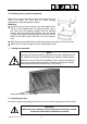
The model 800 is movable. The front castors have provision for locking. In order to assure
stability, the front castors must always be set to the front of the oven for locking.
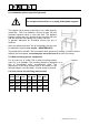
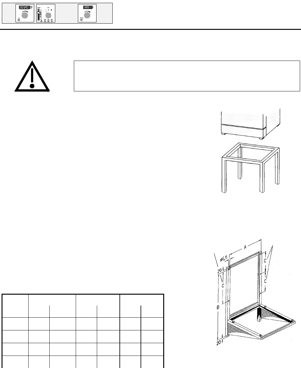
2.3 Wall mounting (special equipment)
For all ovens up to model 700 a metal mounting bracket
(see Fig. a) is available. The mounting bracket is supplied
with a fire-resistant plate. incombustible plate. The
dimensions of the fixing screws have to be chosen to suit
the total weight ( oven and load ) and the quality of the wall.
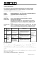
2.4 Hole pitches for wall fixing (wall bracket)
A B
C
model mm
inch
mm inch mm inch
400 489 19,25 850 33.47 - -
500 649 25,55 930 36,61 - -
600 889 35,00 1090 42,91 540 21,26
700 1129 44,45 1250 49,21 410 16,14
model 600
model 700
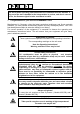
Do not place the steriliser on a readily inflammable support!