0 40 80 120 160 180 200 OPERATING INSTRUCTIONS Electronically controlled drying ovens UP 400-800 ULP 400-800 Electronically controlled sterilisers OPERATING INSTRUCTIONS SLP 400-800 Electronically controlled incubators UP 400 – 800 BP400 400-800 BP - 800 ULP/SLP 400 – 800 UP/BP/ULP/SLP 400 - 800
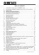
TABLE OF CONTENTS 1 Congratulations on your choice of a MEMMERT Oven! ............................................4 2 2.1 2.2 2.3 2.4 2.5 The equipment of MEMMERT cabinets Series UP, BP, ULP, SLP consists of: ........5 Electrical supply ...................................................................................................... 6 Installation options (special equipment) .................................................................. 8 Wall mounting (special equipment) .......................
14 14.1 14.2 14.3 14.4 Sterilisers ................................................................................................................ 36 Application............................................................................................................. 36 Instructions for sterilisation in MEMMERT hot-air sterilisers. ................................ 36 Notes on working with sterilising cassettes: ..........................................................
The text of these Operating Instructions has been translated from the German. If any part of the text is doubtful or the interpretation is unclear, and also in case of errors, the German original is to be considered as valid. 1 Congratulations on your choice of a MEMMERT Oven! Manufactured in Germany using the latest production techniques and finest materials available, you now possess a technically superior and fully developed product.
2 The equipment of MEMMERT cabinets Series UP, BP, ULP, SLP consists of: an electronic fuzzy-supported microprocessor PID process controller with programmable heating and cooling ramps, set temperature operation and loop function. The controller features continuous power adjustment as well as a time-saving selfdiagnostic system for the quick detection of faults (see check list).
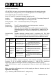
Technical data summary A Pt 100 DIN A in 4-wire circuit measures the temperature in the working chamber. The temperature setting accuracy is 0.1ºC for BP types and 1ºC on UP/SLP types. Ovens Series UP, BP, have natural air circulation. Series ULP and SLP ovens have circulation assisted by a fan. Ambient conditions Ambient temperature 5ºC - 40°C, rH max. 80%. Overvoltage Category II. Contamination degree: 2 according to IEC 664 Setting temperature range 20ºC - to nominal temperature (see rating plate).
model volume current power voltage ±10% weight UP/ULP/SLP 400 53 l 6,1A 1400 W 230 V~ 35 kg UP/ULP/SLP 500 108 l 8,7 A 2000 W 230 V~ 50 kg UP/ULP/SLP 600 256 l 10,4 A 2400 W 230 V~ 87 kg UP/ULP/SLP 700 416 l 5,8 A 4000 W 400 V 3ph/N~ 121 kg UP/ULP/SLP 800 749 l 7,0 A 4800 W 400 V 3ph/N~ 164 kg BP 400 53 l 3,5 A 800 W 230 V~ 35 kg BP 500 108 l 3,9 A 900 W 230 V~ 50 kg BP 600 256 l 7,0 A 1600 W 230 V~ 87 kg BP 700 416 l 7,8 A 1800 W 230 V~ 121 kg BP
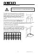
2.2 Installation options (special equipment) Do not place the steriliser on a readily inflammable support! The cabinet can be setup on the floor or on a table (bench), model 500 - 700 on a subframe. Ensure at least 150 mm clearance between back of oven and wall. The distance between ceiling and oven should not be less than 200 mm and the minimum wall spacing to the sides is 80 mm. In general, adequate air circulation around the unit is required.
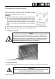
2.5 Stacking device (special equipment) Where two ovens of the same size are to be placed one on top of the other, the oven with the lower working temperature should be placed at bottom . Mounting: Remove the front feet of the top oven and replace them with the ones supplied with the stacking device (only if the ovens are not originally supplied with the stacking device). Remove the top of the bottom oven and turning it upside down place the drilling jig into the back corner.
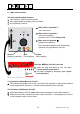
4 Main switch module The main switch module contains: main switch to select the working mode three signal lamps for display of the unit status slot for Memory Card XL Main switch in position 0: unit is shut down Main switch in position I: continuous operation operation from PC with Celsius 2000 Main switch in position programmed operation : Direct operation (without card), alternatively operation using the Memory Card XL Green Ready for operation Red Fault indicator Yellow Unit is heating Insert the
5 Working controller module The working controller can be operated using the digital rotary knob and the set button as described in the following sections. Text messages on the multifunctional LED display guide you through the different menu items. This makes the operation of the P-controller largely self-explanatory. This page gives an overview of the menu structure with its main menu and the sub-menus. On the following pages the menu items and the functions are described in detail.
6 The Memory Card XL 6.1 Programming: A temperature profile with up to 40 ramps can be programmed on the Memory Card XL. Programming can be done directly at the controller or via the PC program " Celsius 2000". It is recommended to use the graphic environment on the PC to build up programs with more than 9 ramps. Labelling: The labelling field of the Memory Card XL can be marked individually with a text or a diagram.
6.3 Programming with the PC program "CELSIUS 2000" Connect the PC to the oven via a shielded serial interface according to DIN 12900-1. (see section – The serial communication Interface) Insert the Memory Card XL into the slot on the oven and press to lock it into place. Move the main switch to position I. Programme the controller settings exactly as described in the manual supplied for the program „Celsius 2000“. The settings are written on the card and stored there.
7 The parallel printer interface All units of the class P are fitted with a parallel interface of the same type as used in personal computers. 7.1 Printer connection All EPSON - LQ or ESC/P2 compatible 24-dot matrix and ink-jet printers can be used. Colour printing is also supported. Green (broken line) = set temperature, red (continuous line) = actual temperature. A parallel 25-pin SUB-D interface serves as connection. It is located on the back of the unit.
Printer mode The menu item PRINT activates the data transmission to the printer. Numerical print numerical printout with GLP header data COMPANY............: EXPERIMENT.......: PAGE 1/_ PROBE-ID.............: UNIT-ID.................: DATE..............: SIGNATURE...
8 Serial communication interface 8.1 Communication protocol The communication protocol of the MEMMERT P-controller was defined following the rules of the association for standards for measurement technology and control engineering in the chemical industry (NAMUR). 8.2 Computer connection For linking your P-appliance to your PC there is an interface connector on the back of the casing of every unit. The oven can be linked to the PC using a shielded interface lead to the connector.
8.4 Interface RS485 If specially ordered, the unit can be fitted at the works with an RS485 interface instead of an RS232C interface. This enables several units (up to 16) to be networked with a PC via a common two-wire connection. By allocating addresses to the individual ovens in the SETUP submenu under the menu item ADRES, the networked ovens are assigned unique number addresses. These can be used to call up the oven and programme it from the PC.
9 Working controller module with main switch in position I (continuous operation) With main switch in position I the oven operates continuously and all adjustments immediately affect the unit operation.
Menu item TEMP to adjust the set temperature. FAN serves to set the speed of the fan in those units which are fitted with one. The setting is carried out in 10% stages. OFF means: fan is switched off completely. FLAP serves to pre-set the air flap in 10% stages. CLOSE means that the air flap is closed, OPEN means that it is fully open but there is no complete fresh-air operation.
9.1 Submenu SETUP After selecting YES under the menu item SETUP you branch to the submenu for the configuration of the controller. Time and date of the integrated real-time clock, the paper feed and the oven address are set here. Note: The return from the SETUP submenu to the actual temperature is achieved by selecting the menu item EXIT/YES or occurs automatically after 30 sec.
time in 24-hour format setting range: 00.00h to 23.59h date in the format day-month. setting range: 01-01 to 31-12, with automatic 30./31. dayswitching, as well as 29th Feb. in leap years. year setting range: 1996 to 2095 line feed The settings 3 hours/page, 12 hours/ page and 7 days/page are possible. address allocation The unit can be allocated an address from 0 to 15. This must agree with the selected address in the PC-controlled software program CELSIUS 2000.
9.2 The working controller module with main switch in position After switching on, the display shows for a few seconds the program version of the controller. prog print edit The unit operates in programme mode if the main switch is set to position . In this operating mode the programme can be started and stopped, and in the submenu EDIT the programme can be changed. The setting will affect the unit operation after the programme is started. The flashing LED prog indicates that the programme is running.
Note ! During programme run (indicated by the flashing of the LED prog) it is impossible to change the selected parameters. Therefore the menu item EDIT is replaced by VIEW. By selecting VIEW / YES the adjusted parameters can be checked but not changed. In the menu item PROG the programme can be started or stopped In the EDIT submenu the programme can be set up or changed (see chapter Editing the programme) Selecting YES in the menu item SETUP opens the submenu for the controller configuration settings.
9.3 Editing the programme / EDIT submenu The programming submenu is opened by selecting YES in the menu item EDIT (or VIEW during programme run). The parameters for each programme segment (max. 9) are set here: Duration (t i m e ), final temperature of the segment (T e m p ), speed of the fan (F a n -if applicable) and the segment end command . The status LED edit indicates that the controller is in the EDIT submenu.
The dynamic operating menu only shows as many programme segments as programmed, i.e. until a programme segment is closed with a programme end command (LOOP, HOLD, END). If the programme end command of the existing last programme segment is replaced by NEXT or SP.WT. an additional programme segment is added (up to 9 segments). Note: The return from any menu to the actual temperature is achieved by selecting the menu item EXIT or occurs automatically after 30 sec.
9.4 Segment end command The programme segments are connected by a segment end command. The end commands determine the programme flow. They also determine how many programme segments are displayed during the programming procedure. Printer(if connected) stops printing "End of the programme" programme flow: At the end of the programme the heating is switched off and all parameters (e.g. fan) are set to the default value. No further programme segment accessible.
10 Programme start A programmed temperature profile can be started as described in the chapter Controller Module with main switch in position . The LED prog on the display of the P-controller is flashing. During the programme run it is impossible to change the selected parameters. The current status can be shown on the controller display by pressing the set button If there is no further action for a few seconds the controller display shows again the current actual temperature.
10.
ϑ 100°C 20°C 1h 2h 15min 1h t FAN FLAP UP/BP/ULP/SLP 400 – 800 29
10.2 Programming example for setpoint-dependent operation An oven with fan has to heat up to 180°C in one hour, with the air flap closed and the fan switched off; on reaching the set temperature it has to hold it for exactly 2 hours and 15 minutes, with the fan running at 40% speed and the air flap closed; the oven then has to cool down to 80°C in 1 hour at maximum fan speed. The 80°C temperature is then held, with the air flap open.
ϑ hold wait 180°C 20°C 1h 2h 15min 1h t FAN FLAP set temperature actual temperature UP/BP/ULP/SLP 400 – 800 31
11 The MEMMERT software „Celsius 2000“ Using the „Celsius 2000“ program: the P-controller can be programmed from the PC and the programme run can be started, the Memory Card XL can be programmed and the programme run can be started, a temperature programme on the Memory Card XL can be overwritten by a new programme sequence, programmes and actual temperature profiles on a Memory Card XL can be loaded, shown on the screen, and stored on another storage medium (hard disk, diskette), several ovens can be contr
12 Safety devices 12.1 Adjustable overheat controller (TWW), Class 3.1 in accordance with DIN 12880 or adjustable temperature limiter (TWB), Class 2 in accordance with DIN 12880 Adjustable overheat controller (TWW), Class 3.1 and adjustable temperature limiter (TWB), Class 2, work independently of the temperature control system in accordance with DIN 12880. The safety devices should be checked at regular intervals, e.g. once a month, once the oven has stabilised at the desired temperature.
Should the temperature rise above the set working temperature, The adjustable overheat controller TWW takes over the temperature control, if the set safety temperature is reached. The adjustable temperature limiter TWB switches off the heating and must be reset by pressing the „alarm set“ button The "alarm" lamp lights up The working controller shows "A L A R M " In this case please check the TWW or TWB as described and readjust it if necessary.
13 Loading Units described in this instruction manual must not be used for drying or heating substances giving off vapours or gases which are inflammable when mixed with air. The units described here must never be operated in areas with an explosive atmosphere. For correct operation and uniform temperature distribution it is essential to maintain free air circulation throughout the oven.
14 Sterilisers 14.1 Application The apparatus is used for sterilising medical materials by employing dry heat through hot air at atmospheric pressure 14.2 Instructions for sterilisation in MEMMERT hot-air sterilisers. There are many different specifications for hot air sterilisation; they cover temperatures and sterilisation times to be selected as well as the packaging of the sterilisation goods.
In particular with heavy loads, these approximate values should not be used without proper testing. In order to ensure safe sterilisation the individual sterilisation process must be validated, using e.g. additional temperature sensors or germ packets. During sterilising the air flap has to be closed after the moist load has been dried. WARNING! Models 700 and 800 are fitted with a door closure mechanism incorporating a lock.
14.4 Example of programming a sterilisation profile The following example shows a possible sterilisation profile. This example uses 60 min at a temperature of 180°C. To programme this temperature profile, select the submenu EDIT, with the main switch in position . ϑ wait wait 180°C The temperature of 180°C has to be reached in 1 minute. End 20°C 1min 1h 1min 1min t FAN FLAP The fan motor runs at maximum speed. set temperature actual temperature The segment closing command S P . W T .
ϑ After the end of the sterilisation time the oven has to cool down to the 50°C unloading temperature in 1 minute. wait wait 180°C End 20°C 1h 1min 1min 1min t The fan motor continues to run at maximum speed. FAN FLAP set temperature actual temperature The segment closing command S P . W T . 3 ensures that the programme is only continued after the temperature of 50°C has been reached.
15 Maintenance General information Memmert ovens require minimal servicing. It is recommended that the moving parts on the doors (hinges and door lock) should be lubricated with thin silicone grease once a year (with continuous use 4 times a year). In case of a malfunction which makes the opening of the unit necessary this work has to be performed by a qualified service engineer. A tightly closing door is an essential requirement for proper operation of the oven.
16 Cleaning Regular cleaning of the (easy to clean) interior prevents the formation of deposits which may impair the appearance and function of the oven. The unit can be cleaned with a commercial stainless steel cleaning agent. Please note that objects liable to rust must not be placed into the interior. Rust deposits lead to contamination of the interior or the external casing.
The details in these Operation Instructions must be carefully observed in order to ensure satisfactory operation. Any warranty and claims for damage are excluded if these instructions are disregarded. We reserve the right to make changes in technical specifications. Dimensions subject to confirmation. Standard ovens (UP / ULP / BP) are safety-approved and bear the test marks: Sterilisers (SLP) are safety-approved and bear the test marks: ref. No.
EC Declaration of Conformity Manufacturer´s name and address: MEMMERT GmbH + Co. KG Äußere Rittersbacher Straße 38 D-91126 Schwabach Product: Universal oven Type: UM … / ULM … / UE ...
EC Declaration of Conformity Manufacturer´s name and address: MEMMERT GmbH + Co.
EC Declaration of Conformity Manufacturer´s name and address: MEMMERT GmbH + Co.
19 Index ........................................................................page .......................................................................page Interface RS232C .............................................16 Interface RS485 ................................................17 interruption of the supply ..................................23 A address .............................................................16 Address ....................................................
R Storage volume for protocol data .................12 subframe .............................................................8 Submenu...........................................................11 Submenu SETUP..............................................20 Readjusting the door ........................................40 real-time clock...................................................20 RS232/RS485 converter...................................17 RS232C interface ............................................
D07981 01.10.