
Owner's manual


10
Design and description
2. Design and description
2.1 Design
1
2
17
18
16
15
13
12
11
10
7
5
4
3
8
9
6
14
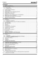
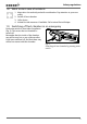
Fig. 3 Design of TTC temperature test chambers and CTC climatic test chambers
1 Controller/operating panel (see page 28 )
2 Main switch / push-turn control (see page
27 )
3 Temperature sensor (see page 21 )
4 Laptop (optional) (see pages 21 and 43 )
5 Laptop holder (special accessories, see
page 21 )
6 Chamber fan
7 Chamber seal
8 Interior for chamber load
9 Fan/air filter of cooling unit (see page 63 )
10 USB connection/ communication inter-
faces (see also Fig. 4 and page 55 )
11 Additional socket 230 volt/max. 5 amp.
(see also Fig. 4 )
12 Locking swivel castors
13 Drawer for water tank with document
compartment (only for CTC climatic test
chambers, see page 22 )
14 Nameplate (see page 16 )
15 Door seal
16 Door
17 Handle to open and close door (see page
25 )
18 Side feed-through to chamber, 80 mm
diameter