OPERATING MANUAL Climatic test chamber CTC 256 Temperature test chamber TTC 256
Manufacturer and customer service MEMMERT GmbH + Co. KG Postfach 17 20 D-91107 Schwabach Äußere Rittersbacherstr. 38 D-91126 Schwabach Germany Fon: +49 (0) 09122 / 925-0 Fax: +49 (0) 09122 / 14585 E-Mail: sales@memmert.com Internet: www.memmert.com Customer service: Fon: +49 (0) 09122/925-128 and: +49 (0) 09122/925-126 E-Mail: service@memmert.com For service enquiries, please always specify the appliance number on the nameplate (see page 16). © 2013 Memmert GmbH + Co.
About this manual About this manual Purpose and target group This manual describes the setup, function, transport, operation and maintenance of temperature test chambers of the type TTC 256 and climatic test chambers of the type CTC 256. It is intended for use by the trained staff of the operator who are in charge of operating and / or maintaining the test chamber. If you as the operator are asked to work on the test chamber, you should read this manual carefully before starting work on the unit.
Content Content 1. Safety regulations 6 1.1 Terms and symbols used ..................................................................................................... 6 1.1.1 Terms used ..................................................................................................................... 6 1.1.2 Symbols used................................................................................................................. 6 1.2 Product safety and dangers ...................................
Content 5.6 Basic operating information.............................................................................................. 27 5.6.1 Switching appliance on and off .................................................................................. 27 5.6.2 Operating panel/ controller ......................................................................................... 28 5.6.3 Basic operation .......................................................................................................
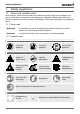
Safety regulations 1. Safety regulations 1.1 Terms and symbols used In this manual, certain common terms and symbols are used to warn you of dangers or to give you hints that are important in avoiding injury or damage. Observe and follow these hints and regulations to avoid accidents and damage. These terms and symbols are explained below. 1.1.1 Terms used „Warning“ is used whenever you or somebody else could be injured if you do not observe the accompanying safety regulation.
Safety regulations 1.2 Product safety and dangers Temperature test chambers of type TTC and climatic test chambers of type CTC are technically advanced, manufactured using high-quality materials and are tested for many hours in the factory. The test chambers are state-of-the-art technology and comply with recognised technical safety regulations. However, there are still dangers involved, even when the appliance is used as intended. These dangers are described below.
Safety regulations 1.4 Requirements of the operating personnel The test chamber may only be operated and maintained by persons who are of legal age, and who have received instructions for the test chamber. Personnel who are to be instructed or who are undergoing general training may only work with the test chamber under the continuous supervision of an experienced person.
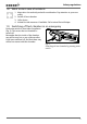
Safety regulations 1.8 What to do in case of accidents 1. Keep calm. Act resolutely and with consideration. Pay attention to your own safety. 2. Switch off test chamber. 3. Call a doctor. 4. Initiate first aid measures. If available: Call a trained first aid helper. 1.9 Switching off test chamber in an emergency Push main switch on front side of appliance (Fig. 2). This causes the test chamber to switch off.
Design and description 2. Design and description 2.1 Design 1 2 3 4 18 17 5 6 7 8 16 15 14 9 10 11 13 12 Fig. 3 Design of TTC temperature test chambers and CTC climatic test chambers 1 Controller/operating panel (see page 28) 11 Additional socket 230 volt/max. 5 amp. 2 Main switch / push-turn control (see page (see also Fig.
Design and description 7 6 5 1 4 2 3 Fig. 4 Connection panel at bottom left of appliance base (see Fig. 3, Items 10 and 11) 1 Socket 230 volt/max. 5 A 2 Floating switch contact SP = setpoint reached for message that the temperature in the chamber lies within a tolerance range of ± 2 K. Load capacity 24 volt/2 amp. (optional) 3 Floating switch contact alarm for error display. Load capacity 24 volt/2 amp.
Design and description Important: The relative air humidity can only be set in the temperature range of 10 °C to 95 °C. The CTC climatic test chamber has two freshwater tanks with automatic switchover (see page 22). The currently active tank is indicated in the control display by “TANK1” or “TANK2” (see page 28). 2.3 Working range Caution: If in operation at the upper level or outside the working range for long periods, puddles of water may form inside the chamber and water may pass the door seal.
Design and description 200,0 98% 158 °C 150,0 90% 100,0 50,0 0,0 00:00 -18 °C -50,0 Fig. 8 0% 00:10 00:20 00:30 00:40 10% Warm-up time Warm-up speed 2.4 Basic equipment FCKW-free cooling unit with automatic hot gas defrosting device and motor-driven air circulation in the chamber ► Electronic fuzzy-supported PID process controller with permanent performance adjustments and time-saving self-diagnosis system to quickly locate errors (see chapter chapter 6.
Design and description ► Calibration certificates for temperatures at –20 °C and +160 °C and for humidity at 30 °C ► ► ► ► ► ► ► ► ► ► ► and 60 % rh A pre-formatted empty MEMoryCard XL with a storage capacity of 32 kByte. Reprogrammable for up to 40 ramp segments and in addition 135 hours of log memory for temperature and humidity, with a scan interval of 1 minute (see page 58).
Design and description 2.7 EC Declaration of Conformity EC De eclaration of Conformitty Manufacturer’s name and addresss: MEMMERT GmbH + Co. KG Äußere Rittersbacher Straße 38 91126 Schwabach, Germany mbers limatic Testing Cham CTC...
Design and description 2.8 Designation (nameplate) The nameplate provides information about the appliance model, manufacturer and technical data. It is attached to the front of the appliance, on the right beneath the interior (see page 10). 1 9 2 3 8 4 7 5 6 Fig.
Design and description 2.9 Technical data Type TTC 256 CTC 256 Chamber width A* [mm] 640 Chamber height B* [mm] 670 Chamber depth C* [mm] 597 Appliance width D* [mm] 898 Appliance depth F* [mm] 1100 Appliance height E* [mm] 1730 Chamber volume [liter] 256 Weight [kg] ≤ 320 Performance [W] ≤ 350 7000 max. number of sliding grates 6 max. load per sliding grate [kg] 25 max. load per appliance [kg] 100 Temperatures min/max.
Design and description F D A C E B 80 Fig. 10 Dimensions of CTC/TTC test chambers 2.10 Environmental conditions ► The test chamber may only be used in enclosed rooms and under the following environ- mental conditions: Ambient temperature: 16 ºC to 28 ºC Air humidity: max. 70 % not condensing degree of pollution: 2 Altitude of installation max. 2000 m above sea level ► The test chamber may not be used in areas where there is a risk of explosions.
Delivery, Transport and Setting Up 3. Delivery, Transport and Setting Up 3.1 Safety Regulations Warning! You may get your hands or feet squashed when transporting and installing the test chamber. Wear protective gloves and work shoes. Warning! Because of the weight of the chamber, you could get injured if you try to lift it. Transport the test chamber only with a fork-lift truck, manual pallet jack or on its castors.
Delivery, Transport and Setting Up 3.4 Transport The test chamber can be transported in three ways: ► on its own castors, for which the catch on the (front) castors must be released ► with a fork-lift truck; move the forks of the truck entirely under the test chamber ► on a manual pallet jack Caution: If the test chamber is to be transported again after it has been put into operation, for example at a different location: First empty the freshwater and condensation water tanks (see page 22). 3.
Putting into Operation 4. Putting into Operation Caution: The test chamber may not be put into operation before 24 hours after installation at the point of operation, so that any oil that may have penetrated the tubing can flow back into the compressor of the cooling unit and return to room temperature. 4.1 Checking the door and adjusting if necessary A well-closing door is indispensable for temperature and climatic test chambers. The door may have been twisted during transport.
Putting into Operation 4.4 Filling the freshwater tanks (only for CTC 256 climatic test chambers) Water specifications For steam generation, use only: ► Steam-distilled water (aqua dest) or ► Demineralised water (aqua dem) in accordance with VDE 0510/DIN EN 50272; regulations must be strictly adhered to (production conductivity ≤ 10 μS/cm). Battery water in accordance with VDE 0510 is available in larger chemist’s shops, super markets, hardware stores and in the wholesale trade.
Putting into Operation 4.5 Connecting Caution: Observe the country-specific regulations when making connections (e.g. in Germany DIN VDE 0100 with an RCD circuit breaker). Also observe the connected loads and power values (see chapter 2.9 Technical data on page 17). The test chamber is intended for operation on an electrical power system with a system impedance Zmax at the point of transfer (service line) of a maximum of 0.292 Ohm.
Operation and control 5. Operation and control 5.1 Operating staff The test chamber may only be operated by persons who are of legal age, and who have received instructions for the test chamber. Personnel who are to be instructed or who are undergoing general training may only work with the test chamber under the continuous supervision of an experienced person. 5.
Operation and control 5.4 Opening and closing the door Danger! When opening the chamber door, hot steam may escape and scald you in the face if the test chamber was in operation directly before this. Remain behind the door when you open it and let out the steam, or allow the test chamber to cool down before opening the door. Warning! Depending on operation, the surfaces in the chamber interior, the viewing window and the chamber load may be very Fig. 17 hot or very cold.
Operation and control 5.5 Loading the test chamber Warning! When loading the chamber with an unsuitable load, toxic or explosive vapours or gases may be produced. This could cause the chamber to explode, and people could be badly injured or poisoned. The chamber may only be loaded with materials/test objects which do not form any toxic or explosive vapours when heated up and cannot ignite (see also chapter 2.6 Intended Use on page 14).
Operation and control 5.6 Basic operating information 5.6.1 Switching appliance on and off The test chamber is switched on and off by pressing the main switch/push-turn control on the front of the appliance. ► Switching on: press the main switch so that it comes out of the appliance (Fig. 19). ► Switching off: press the main switch so that it retracts back into the appliance (Fig. 20). Fig. 19 Switching on test chamber Fig.
Operation and control 5.6.2 Operating panel/ controller In normal and programme modes the desired parameters are entered on the operating panel of the controller on the front of the appliance (Fig. 21). Basic settings, as well as those for time and printing, can also be made here.
Operation and control 5.6.3 Basic operation set All operating functions are selected by turning the push-turn control to the left or right ... ... ... and adjusted by turning it with the SET key held down. set 5.6.4 Setting parameters Normally, all setting actions on the operating panel described on the following pages are made in the same way: 1. Select the desired parameter with the push-turn control (menu item, e.g. set temperature), then all other parameters go dark and the selected one flashes.
Operation and control Normal mode (see page 30) Fig. 22 Week time switch (see page 33) Operating modes Programme mode (see page 35) PRINT SETUP Printer (see page 46) Basic appliance settings (see page 46) 5.8 Operating mode - settings 1. Switch on appliance by pressing the main switch (main switch comes out of appliance, see Fig. 19). set set set set 2. Hold SET key down for approx. three seconds, the selected operating mode then begins to flash. 3.
Operation and control Temperature monitoring Adjustment range:: MIN MAX AUTO (see also page 48) °C MAX MIN AUTO Humidity setpoint %rh (only for CTC 256) Adjustment range: 10 to 98 %rh, off Not all combinations of temperature and humidity are possible (see also Fig. 5 on page 12). 5.8.2 Example setting Normal mode 160 140 120 100 80 60 40 Temp. monitoring MAX Temp.
Operation and control 1. Setting the normal operating mode: Hold SET key down for approx. 3 seconds, the current operating mode then begins to flash. Select the operating mode with the push-turn control, while the SET key is held down. After you let go of the SET key, the control is in the normal operating mode. SETUP PRINT 2. Setting the temperature setpoint: Hold down the SET key and set the desired temperature setpoint of 50.0 °C.
Operation and control 5.8.3 Week time switch In this operating mode, the week time switch is PRINT SETUP active and the test chamber switches on and off at the time programmed. During the OFF phase of the week time switch, the test chamber is in standby mode. The heating and cooling functions are switched off here and the controller display shows the time, dimmed. During the ON phase, the test chamber works with the set values for temperature, humidity, etc.
Operation and control Direct setting of the temperature setpoint: If the controller is in standby mode or the week time switch is in the ON phase, the temperature setpoint can be directly accessed by briefly pressing the SET key. By turning the control to the right, you are returned to temperature monitoring and humidity. By turning to the left you come back to the settings for the individual time blocks. 5.8.4 Example of settings Week time switch Fig.
Operation and control 3. Switch off Mo-Fr at 18:00 Select “Mo-Fr off” (group working days) with the pushturn control. Hold down the SET key and set the desired switch-off time to 18:00 with the push-turn control. Mo Tu Th We Fr on h off 4. Switch on Sa at 10:00 Select “Sa on” with the push-turn control. Hold down the SET key and set the desired switch-on time to 10:00 AM with the push-turn control. Mo Tu Th We Fr h off Mo Su Sa on 5.
Operation and control Mo Tu We Th Fr Sa on 4 t4 t2 h off t3 Su t1 STERI loop IN 1 DEFRO °C 3 2 1 OUT %rh °C mb MAX MIN AUTO SETUP PRINT IN 2 5. Delayed programme start: Switch-on time Adjustment range: 00.00 to 23.59 (shown in picture: Switch-on time 8:00) If no switch-on day is selected, then no switch-on time can be selected, and the programme starts immediately ( instant start).
Operation and control Each ramp must be completed with a close command connecting the ramp to the next one. These commands thus control the programme sequence: Tu Mo We Th Fr Sa on 4 t4 t2 h off t3 Su STERI t1 loop IN 1 DEFRO °C 3 2 1 OUT %rh °C mb MAX MIN AUTO SETUP PRINT IN 2 10. Close command of the ramp segment Setting: NEXT, SPWT (T), SPWT (H), SPWT (TH), LOOP, HOLD, END (shown in picture: Command End; see also chapter 5.8.6 Close commands for ramp segments on page 37).
Operation and control SET-POINT WAIT (H – humidity, only for CTC 256) Wait until setpoint humidity has been reached. Appliance starts the next programme segment only when the programmed setpoint humidity has been reached, even if the set heating up time has already elapsed. SET-POINT WAIT (TH – temperature and humidity, only for CTC 256) Wait until setpoint temperature and setpoint humidity have been reached.
Operation and control 5.8.7 Example setting programming mode For the TTC temperature test chamber there is no programming of humidity. On Monday at 8.00, the test chamber should heat up to 50 °C as quickly as possible, with a fan speed of 40 %, and reach a relative humidity of 70 % rh. Once the temperature and humidity have been reached, the test chamber should retain the setpoint values for 45 minutes and then cool down within one hour to a humidity of 50 % rh and 37 °C (Fig. 26).
Operation and control 1. Setting the programming operating mode: Hold the SET key down for approx. 3 seconds, the current operating mode then begins to flash. Select the programming mode operating mode with the push-turn control, while the SET key is held down. After releasing the SET key, the control is in the programming operating mode. PRINT 2. Editing the programme: Select EDIT with the push-turn control, while the SET key is held down.
Operation and control 8. Setting the relative humidity of the first ramp segment (only for CTC 256): Turn the push-turn control to the right until the humidity display flashes. Hold down the SET key and set the desired humidity setpoint of 70.0 % rh with the push-turn control. %rh 9. Setting the close command of the first ramp segment: Turn the push-turn control to the right until a segment close command appears, e.g. end.
Operation and control 15. Setting the duration of the third ramp segment: Select the time display with the push-turn control. Hold down the SET key and set the time to 01:00:00 AM with the push-turn control. h 16. Setting the temperature of the third ramp segment: Turn the push-turn control to the right until the temperature display flashes. Hold down the SET key and set 37.0 °C with the pushturn control. °C 17.
Operation and control 5.8.8 Operation with PC/laptop (optional) The test chamber can optionally be used, controlled and programmed with a PC/laptop. It has corresponding communication interfaces for this purpose (see page 55 and Fig. 3 on page 10). The control of the appliance with the Memmert-PC software “Celsius” is described in its own separate manual. 5.9 Ending operation Warning! When opening the chamber door, hot steam may escape and scald you in the face.
Malfunctions and error messages 6. Malfunctions and error messages Warning! After removing covers, voltage-carrying parts may be exposed. You may receive an electric shock if you touch these parts. Malfunctions requiring intervention inside the appliance may only be rectified by electricians. Read the separate service manual for this.
Malfunctions and error messages Error Possible causes Rectification Insufficient cooling power Air inlet/outlet blocked Ensure that the fan opening on the front side of the appliance is not covered (see page 10) Air filter soiled Clean air filter (see page 63) Cooling unit iced up Set shorter defrosting intervals in SETUP - Defrost (see Kapitel 7.
Advanced functions 7. Advanced functions 7.1 Printer The test chamber is equipped with a parallel printer port as standard, just as used in computers. A standard PCL3-compatible inkjet printer which has a parallel port interface (e.g. HP DeskJet 5550 or HP DeskJet 9xx) can be connected to the printer port on the left of the test chamber (see page 11). Make sure that a shielded interface cable is used. The shielding must be connected to the plug casing.
Advanced functions Date The controller contains a calendar which automatically accounts for the different lengths of months, and for leap years. Weekday Tu Year Adjustment range: From 2000 to 2100 Acoustic signal at programme end ENDSOUND Setting: OFF oder ON Acoustic signal for alarm, e.g. over/undertemperature ALARM sound Setting: OFF or ON Communication address Adjustment range: 0 bis 15 (see Chapter 7.
Advanced functions 7.3 Temperature monitoring and safety equipment The monitoring temperature is measured via a separate Pt100 temperature sensor in the chamber interior. The monitoring unit is used to protect the chamber load and as a protection for the appliance and surroundings. Temperature monitoring can be adjusted independently of the operating modes. Im ramp operation mode the monitoring temperature must always be set at least 3 K above the maximum working temperature.
Advanced functions Undertemperature limit Adjustment range: -50 ... +200 °C °C Setting: MAX Select the MIN icon with the push-turn control. Hold down the SET MIN key and adjust the temperature limits with the push-turn control. AUTO The lower alarm limit value cannot be set higher than the top one. If no undertemperature limit is required, set the lowest temperature.
Advanced functions The ASF alarm goes off automatically as soon as 50 % of the set tolerance band of the setpoint (in the example 50 °C ± 1 °C) is reached again (section A). If the temperature setpoint is altered, the ASF is automatically disabled temporarily (see in the example: The setpoint is changed from 50 °C to 25 °C, section D), until it has reached the tolerance range of the new temperature setpoint (section E).
Advanced functions 7.3.3 Warning messages A repeated acoustic signal indicates an error in the temperature control system or in the humidification system. It is set off in the following cases: Overtemperature limit is triggered. Check the MAX setting and increase if necessary (see Chapter 7.3.1 Electronic temperature monitoring (TWW) on page 48). Undertemperature limit is triggered. Check the MIN setting and reduce if necessary (see Chapter 7.3.1 Electronic temperature monitoring (TWW) on page 48).
Advanced functions CAL 3 +0,8 °C tory CAL 1 +0,5 °C -40 °C Fig. 30 CAL 2 -0,4 °C fac n at tio bra Cali 30°C 150 °C Temperature calibration (example) Setting: 1. Set the desired compensation temperature in the SETUP (see Chapter 7.2 Basic appliance settings (Setup) on page 46) and set the corresponding compensation correction value to 0.0 °C. 2. With a reference instrument, measure the deviation in the stationary state in the selected compensation temperature. 3.
Advanced functions 4. The reference instrument should now display 30 °C after the calibration procedure. 5. With CAL.1, another compensation temperature below CAL.2 can be programmed in the same way, and with CAL.3, one above it. If all compensation correction values are set to 0.0 °C, the factory calibration settings are restored. 7.4.2 Humidity calibration (only for CTC 256) The test chamber can be calibrated for the individual customer by means of two balance points at 20 and at 90 % relative humidity.
Advanced functions 2. With a calibrated reference instrument, an actual humidity of 88 % rh is measured at normal operation, with a set setpoint humidity of 90 %rh. 3. Set the compensation correction value in the SETUP for RH 90 to -2.0 %rh: Mo Tu We Th Fr Sa t3 Su on off 4 t4 t2 t1 STERI DEFRO 3 loop 2 1 PRINT SETUP IN 2 °C °C OUT %rh mb IN 1 IN 2 OUT CO2 mb MAX MIN AUTO 4. The reference instrument should display 90.0 % rh after the calibration procedure.
Advanced functions 7.6 Communication interfaces Depending on the specifications, the test chamber can be fitted with different communication interfaces (USB, RS 232/485, Ethernet). These are located on the left side of the appliance, in the base (see Fig. 3 on page 10 and Fig. 4 on page 11). 7.6.1 USB interface The chamber is fitted by default with a USB interface in accordance with the USB specification. With this interface, it is possible to control and log the chamber remotely from the PC.
Advanced functions 7.6.3 Connection of test chambers to a network with Ethernet interface The test chamber can optionally be equipped with an Ethernet instead of a USB interface. LAN 3: 192.168.1.241 LAN 2: 192.168.1.215 LAN 1: 192.168.1.233 192.168.1.216 Fig. 32 Connecting one or more test chambers to a network using an Ethernet interface (schematic diagram) For identification purposes, each appliance connected must have its own unique IP address.
Advanced functions 7.6.4 Log memory The controller continually logs all relevant measured values, settings and error messages at 1-minute intervals. The internal log memory is listed as a ring memory, i.e. the oldest log data are always overwritten automatically with new data. The logging function cannot be switched off, but is always active. The measured data are stored in the controller, safe from manipulation.
Advanced functions 7.6.5 MEMoryCard XL On the MEMoryCard XL (Fig. 33) a temperature control programme with up to 40 ramp segments can be set up (see page 35). This can be programmed directly on the controller or via the “Celsius” software. To programme the MEMoryCard XL with the PC and the “Celsius“ software, please read the user manual for “Celsius” or the online help. For the sake of retaining an overview, it is Fig. 33 MEMoryCard XL recommended that you programme large programmes graphically on the PC.
Advanced functions Programming the MEMoryCard XL from the PC with read-write device Using the card reader which can be purchased separately (Fig. 34), the MEMoryCard XL can be programmed offline from the PC with “Celsius” without the need for a test chamber being connected. When you do this, make sure that the contacts on the MEMoryCard XL are pointing upwards to the markings on the card reader. Fig.
Advanced functions 7.6.6 User ID card (optionally available as an accessory) The device number of the appliance and a unique user number are stored in encrypted form on the user-ID card (Fig. 35). The user-ID card therefore works only in the appliance with the corresponding serial number. Every login process with the user-ID card is Name: logged in the internal Flash memory of the _____________________ access ID: authority controller.
Maintenance and Servicing 8. Maintenance and Servicing Warning! Depending on operation, the surfaces in the chamber interior may be very hot or very cold. You could suffer from burns or frostbite if you touch these surfaces. Before any maintenance / cleaning work, allow time for the chamber interior to reach room temperature. Warning! Disconnect the power plug before any cleaning or maintenance work. 8.
Maintenance and Servicing A Fig. 36 Dismantling the right and left inner walls. Remove the silicone plugs and 8 screws on each side and pull out the wall. Fig. 37 Pull the temperature sensors (A) out of the holders and unscrew the test chamber rear wall 8.3 Regular maintenance Every three months if in permanent operation ► Grease the moving parts of the doors (hinges and lock) with thin silicone grease and check that the hinge screws are not loose.
Maintenance and Servicing 8.4 Adjust door A well-closing door is indispensable for temperature and climatic test chambers. On Memmert appliances, the tight closing of the door is optimally guaranteed by a chamber seal and door seal. In permanent operation, it is possible that the flexible seal material will settle. To ensure that the door closes exactly despite this, an adjustment may be necessary: 1. Undo the grub screw with a Torx-TX8 tool (Fig. 39).
Maintenance and Servicing 8.6 Replacing the interior lamps 1. Undo the four fixing screws of the glass plate on the ceiling of the interior and remove the glass plate (Fig. 43). 2. Replace the defective lamp with a standard new 25 watt halogen lamp. 3. Screw the glass plate back on. Make sure that the seal is properly mounted. 8.7 Repairs and Service Fig. 43 Interior lighting Warning! After removing covers, voltage-carrying parts may be exposed.
Storage and disposal 9. Storage and disposal 9.1 Storage The test chamber may only be stored under the following conditions. ► dry and in an enclosed, dust-free room ► frost-free ► disconnected from the power supply Before storage, empty the freshwater and condensation water tanks (see page 22). 9.2 Disposal This product is subject to the Directive 2002/96/EC on Waste Electrical Electronic Equipment (WEEE) of the European Parliament and of the EU Council of Ministers.
Index Index A Accidents 9 Acoustic signal 47 Adjust door 63 Air circulation 17 Air filter 62, 63 Air humidity 18 ALARM sound 47 Altitude of installation 18 Ambient temperature 18 Appliance errors 44 ASF 49 Automatic defrosting system 47, 54 Automatic temperature monitor 49 B Basic appliance settings 46 Basic equipment 13 Basic operation 29 C Cable feed-through 26 Calibration 51 Card reader 59 CD-ROM 56 Celsius 55 Cleaning the air filter 63 Clearance 20 Clock time 46 Close command of the ramp segment 37 C
Index O S U Opening and closing the door 25 Operating modes 29 Operating mode - settings 30 Operating panel 28 Operating personnel 8 Operating staff 24 Operating voltage 17 Operation 24 Safety class 17 Safety equipment 48 Safety Labelling 7 Safety regulations 6 Service 64 Servicing 61 SET-POINT WAIT 37 Setting parameters 29 Setting Up 19 Setup 46 Standard accessories 18 Storage 65 Storage after delivery 19 Storage space 59 Switching appliance on and off 27 Switch-on time 36 System/ appliance errors 44
Memmert GmbH + Co KG | Postfach 1720 | D-91107 Schwabach | Tel. +49 (0) 9122-925-0 | Fax +49 (0) 9122-145-85 | E-Mail: service@memmert.com | www.memmert.com 18.02.