OPERATING MANUAL CO2 incubators INCO 108 INCO 153 INCO 246 INCO 108 med INCO 153 med INCO 246 med
Manufacturer and customer service MEMMERT GmbH + Co. KG Postfach 17 20 D-91107 Schwabach Äußere Rittersbacherstr. 38 D-91126 Schwabach Germany Fon: +49 (0) 09122 / 925-0 Fax: +49 (0) 09122 / 14585 E-Mail: sales@memmert.com Internet: www.memmert.com Customer service: Fon: +49 (0) 09122/925-128 and: +49 (0) 09122/925-126 E-Mail: service@memmert.com For service enquiries, please always specify the appliance number on the nameplate (see page 18). © 2012 Memmert GmbH + Co.
About this manual About this manual Purpose and target group This manual describes the setup, function, operation and maintenance of CO2 incubators of the types INCO and INCOmed with a chamber volume of 108, 153 and 246 litres. In this manual, the term INCO is used for INCO as well as INCOmed for the purpose of simplification. Distinctions are explicitly pointed out. This manual is intended for use by the trained staff of the operator in charge of operating and/or maintaining the incubator.
Content Content 1. Safety regulations 1.1 1.2 1.3 1.4 1.5 1.6 1.7 1.8 Terms and icons used .......................................................................................................... 6 Product safety and dangers ................................................................................................ 7 Requirements of the operating personnel .......................................................................... 8 Responsibility of the owner......................................
Content 7. Advanced functions 7.1 7.2 7.3 7.4 7.5 7.6 7.7 7.8 Printer ............................................................................................................................... 45 Basic appliance settings (Setup) ........................................................................................ 45 Temperature monitoring .................................................................................................. 47 Sterilisation chipcard ..................................
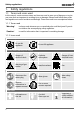
Safety regulations 1. Safety regulations 1.1 Terms and icons used In this manual, certain common terms and icons are used to warn you of dangers or to give you notes that are important in avoiding injury or damage. Observe and follow these notes and regulations to avoid accidents and damage. These terms and icons are explained below. 1.1.1 Terms used "Warning" is always used whenever you or somebody else could be injured if you do not observe the accompanying safety regulation.
Safety regulations 1.2 Product safety and dangers Incubators of the INCO type are technically well-developed, manufactured using high-quality materials and tested for many hours in the factory. They contain the latest technology and comply with recognised technical safety regulations. But there are still dangers involved, even when the appliance is used as intended. These dangers are described below. Warning! After removing covers, live parts may be exposed.
Safety regulations 1.3 Requirements of the operating personnel The incubator may only be operated and maintained by persons who are of legal age, and who have received instructions for the incubator. Personnel who are to be trained, instructed or who are undergoing general training may only be active on the incubator under the continuous supervision of an experienced person.
Safety regulations 1.7 What to do in case of accidents 1. Keep calm. Act resolutely and with consideration. Pay attention to your own safety. 2. Switch off the incubator and close the valves on the gas bottle. 3. Call a doctor. 4. Initiate first aid measures. If available: Call a trained first aid helper. In case of contact with CO2 to the eyes and skin: Rinse eyes out with water for at least 15 minutes. With cold burns, rinse with water for at least 15 minutes. Cover over in a sterile manner.
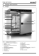
Design and Function 2. Design and Function 2.1 Design 1 2 3 18 4 5 6 7 17 8 16 9 10 11 12 13 15 14 Fig.
Design and Function 2.2 Function The air in the incubator is heated up by an all-round heater with a large surface (Fig. 3, No. 1). The CO2 and/or N2 gas is introduced into the working chamber via a sterile filter. Because CO2 has a much higher specific weight than air, the gas is let into the working chamber above the interior fan (2). The turbulence-free interior ventilation (3) ensures a uniform distribution of the gases, creating a homogenous atmosphere.
Design and Function ► Digitalised electronic CO2 control with automatic zero position, NDIR measuring system ► ► ► ► ► ► ► ► ► ► ► with self-diagnosis system and acoustic error display, air pressure compensation Language settings (see page 46) Alphanumeric text display Integrated week time switch with grup function (e.g.
Design and Function 2.4 Material For the outer housing, MEMMERT uses stainless steel (W.St.No. 1.4016), and for the interior, stainless steel (W.St.No. 1.4301), which stands out through its high stability, optimal hygienic properties and corrosion-resistance towards many (but not all!) chemical compounds (caution for example with chlorine compounds). The chamber load for the appliance must be carefully checked with respect to chemical compatibility with the materials mentioned.
Design and Function 2.6.1 Electrical connection Observe the country-specific regulations when making connections (e. g. in Germany DIN VDE 0100 with residual current device). This appliance is intended for operation on an electrical power system with a system impedance Zmax at the point of transfer (service line) of a maximum of 0.292 ohm. The operator must ensure that the incubator is operated only on an electrical power system that meets these requirements.
Design and Function 2.7.
Design and Function 2.8 EC Declaration of Conformity EC Declaration of Conformity Manufacturer´s name and address: MEMMERT GmbH + Co.
Design and Function EC Declaration of Conformity Manufacturer's name and address: MEMMERT GmbH + Co. KG Äußere Rittersbacher Straße 38 91126 Schwabach, Germany Incubators INCO med 108 l / 153 l / 246 l AC 230 V 50/60 Hz Product: Type: Sizes: Rated voltage: This product complies with the provisions of the directive: 93/42/EEC including annex and revisions Council Directive on the approximation of the laws of the Member States relating to medical devices of 14 June 1993 (Official Journal of the EC No.
Design and Function 2.9 Designation (nameplate) The nameplate (Fig. 5) provides information about the appliance model, manufacturer and technical data. It is attached to the front of the appliance, on the right beneath the door (see page 10). 1 2 3 Typ: INC 108 230 V ~ DIN12880-Kl.3.1 F.-Nr.: 0109.0088 4.4 A 50/60 Hz 1000 W Nenntemp.: 50 °C 10 9 8 4 7 5 6 Fig.
Design and Function 108 153 246 Max. load per sliding shelf [kg] 15 15 15 Max. load per appliance [kg] 40 40 60 Model * See Fig. 6 on page 20. Temperature Temperature recording by means of Pt100 in a 4-wire circuit Adjustment range: Normal mode: 20 °C to 50 °C Sterilisation mode: 160 °C (4 hours) via STERICard Adjustment precision: 0.1 °C Control range: from 8 °C above room temperature to 50 °C Variation (time): max. ±0,1 °C at 37 °C Variation (spatial): max. ±0.
Design and Function D A F C 75 38 202 75 Fig. 6 76 12 8 B E 38 Dimensions of INCO incubators 2.11 Ambient conditions ► The incubator may only be used in enclosed rooms and under the following environmental conditions: Ambient temperature: 5 ºC to 35 ºC Humidity: max. 80 % not condensing Degree of pollution: 2 Altitude of installation max. 3,000 m above sea level ► The incubator may not be used in areas where there is a risk of explosions.
Delivery, Transport and Setting Up 3. Delivery, Transport and Setting Up 3.1 Safety regulations Warning! You may injure your hands or feet when transporting and installing the incubator. You should wear protective gloves and work shoes. Warning! Because of the weight of the incubator, you could injure yourself if you try to lift it on your own. If possible, only transport the incubator with a fork-lift truck or manual pallet jack.
Delivery, Transport and Setting Up 3.3.4 Storage after delivery If the incubator is initially to be stored after delivery: Read the storage conditions from page 65. 3.4 Setup Fig. 7 22 FP The incubator can be placed either on the ground or on a table (work surface). When doing this, ensure that the appliance is positioned exactly horizontally. The installation site must be level and able to reliably carry the weight of the incubator (see page 18).
Delivery, Transport and Setting Up 3.4.1 Base (accessory) The incubator can be placed on a base (Fig. 8). 3.4.2 Stacking frame (accessory) Two appliances of the same model size can be placed on top of one another. To do this, foot alignment provisions must be attached to the lower oven (Fig. 9): 1. Remove the housing cover from the lower oven. 2. Insert drilling template (supplied with the foot alignments) into the overturned lid. 3. Mark drilling points and drill with a 4.2 mm diameter drill bit. 4.
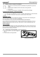
Putting into Operation 4. Putting into Operation 4.1 Checks 4.1.1 Checking the temperature sensor Especially strong vibrations during transport could result in the temperature sensors being moved in their holders in the working chamber. Check the temperature sensor for its correct positioning and if necessary adjust its position in the holder (Fig. 10). 4.1.2 Check the door and adjust if necessary See page 64. 4.2 Connecting 4.2.1 Power supply Fig.
Putting into Operation 4.2.4 Gas connection Warning! Danger of suffocation: In high concentrations, CO2 and N2 can have a suffocating effect. In normal operation, the incubator gives off small amounts of CO2 and – if equipped with the O2 module – N2 to its environment. You should therefore ensure that the room in which it is installed is properly ventilated. Warning! High concentrations of CO2 can cause cold burns or frostbite. Avoid contact with CO2 gas to the eyes and skin.
Putting into Operation For incubators with O2 module: ► Attach the supplied CO2 pressure hose to the CO2 gas bottle (pressure reducer) and to the “CO2 In” connection on the rear of the incubator with a hose clamp (Fig. 13, see also page 13). ► Attach (push on) the supplied N2 pressure hose to the N2 gas bottle (pressure reducer) and to the “N2 In” connection on the rear of the incubator with a hose clamp. 4.
Operation and control 5. Operation and control 5.1 Operating personnel The incubator may only be operated by persons who are of legal age and have received instructions for the incubator. Personnel who are to be trained, instructed or who are undergoing general training may only be active on the incubator under the continuous supervision of an experienced person. 5.2 Opening the door open ► To open the door, turn handle to the right (Fig. 14). ► To close, turn door handle to the left.
Operation and control 5.4 Inserting water tray(s) (for appliances with basic fittings) Fill the water tray with distilled water and push into the lowest slot (Fig. 15). INCO model Fig. 15 Number of water trays Filling level in cm for each tray approx. Amount of water in ltr. for each tray approx. 108 1 1.5 to 2.5 1 to 1.5 153 1 1.5 to 2.5 1 to 1.5 246 2 1.5 to 2.5 1 to 1.5 Inserting water tray(s) 5.5 Connect gas supply 1.
Operation and control 5.7 Basic operation The desired parameters are entered on the operating panel of the controller on the front of the appliance (Fig. 18). Basic settings, as well as those for time and printing, can also be made here.
Operation and control The control returns automatically to the main menu if the push-turn key or set key is not operated for approx. 30 seconds. Setting the temperature (Quick adjustment): 1. Hold down the SET key and set the desired temperature setpoint with the push-turn control. 2. Release the SET key The appliance flashes briefly, showing the temperature setpoint. Then the current temperature appears on the display and the controller begins to move to the set temperature. 5.
Operation and control 5.10.1 Normal mode The appliance runs in this operating mode in permanent operation. The desired setpoints for operating the chamber can be selected. The settings have an immediate effect on the functions of the appliance. 1. Load incubator (see page 27). 2. Switch on appliance. To do this, press the push-turn control on the operating panel so that it comes out of the appliance (see Fig. 16 on page 28). 3. Select the normal operating mode with the push-turn control: PRINT SETUP 4.
Operation and control 5.10.2 Settings example normal mode 30 20 10 100 80 60 40 25 20 20 15 15 10 10 5 5 20 Time Fig. 20 25 O2 in % 40 Monitoring temperature CO2 in % 50 Humidity rh in % Temperature in °C With a 5% CO2 content, a 3% oxygen content and a humidity of 96%, the appliance should heat up to 37°C. The monitoring function should respond at 38.5 °C (Fig. 20). Time Time Time Example for normal mode 1. Setting the normal operating mode: Hold SET key down for approx.
Operation and control 4. Setting the humidity setpoint: Turn the push-turn control to the right until the humidity display flashes. Hold down the SET key and set the desired humidity setpoint of 96.0 %rh with the push-turn control. After releasing the SET key, the humidity setpoint briefly flashes. The current humidity value appears on the display and the controller begins to move to the set value. The humidification process is indicated by the icon (only for models with humidity module). %rh 5.
Operation and control Weekday Adjustment range: Day groups Adjustment range: Monday to Sunday Working days Mo-Fr Weekend Sat-Sun No switch on time: ---Appliance not switched on on this day Switch on time (on) Adjustment range: 00:00 to 23:59 hours Mo Tu We Th Fr Sa Su Mo Tu We Th Fr Sa Su Mo Tu We Th Fr Sa Su on off on off h Switch off time (off) on One minute beyond the switch on time up to off h 24:00 By turning further to the right, parameters (temperature, humidity setpoints
Operation and control 5.10.4 Settings example week time switch From Mo-Fr (workdays group), the appliance should switch on at 9.30 and switch off at 19.00. In addition it should work on Saturday from 10.00 to 14.00 (Fig. 21). Fig. 21 9:30h - 19:00h Fr Su 9:30h - 19:00h Th 10:0h 14:00h 9:30h - 19:00h We Sa 9:30h - 19:00h Tu 01:00h 9:30h - 19:00h 12:00h Mo 24:00h Operation with week time switch (example) 1. Setting the week time switch operating mode Hold the SET key down for approx.
Operation and control 4. Switch on Sa at 10:00 With the push-turn control, select "Sat on". Hold down the SET key and set the desired switch-on time with the push-turn switch to 10:00. 5. Switch off Sa at 14:00 With the push-turn control, select "Sat off". Hold down the SET key and set the desired switch-off time with the push-turn switch to 14:00. Mo Tu We Th Fr on h off Mo Tu on off Su Sa We Th Fr Su Sa h 5.10.
Operation and control IN 1 IN 2 OUT CO2 After the setpoint temperature has been reached, the CO2 concentration is displayed in %, depending on the setting. IN 1 indicates that gas bottle 1 is active. Is displayed if the CO2 concentration exceeds the defined setpoint by at least 1 % for more than 3 minutes. If the concentration is higher, the CO2 display and the icon flash. In this case you should open the door for 30 sec. and wait to see if the controller steadily adjusts to the setpoint.
Operation and control To be on the safe side, a freshly filled CO2 gas bottle should always be used. So if the gas in bottle 1 is used up, you connect the opened bottle to IN1 and the newly filled bottle as a reserve bottle to IN2. The hose connection system used by Memmert shuts off automatically if a connection hose is pulled off. You should still always close the stop valve on the gas bottle if a bottle is empty or not connected. IN 1 lights up when gas bottle 1 is active.
Operation and control 5.12 Ending operation 1. Switch off appliance. To do this, press the main switch on the operating panel so that it clicks into place in the appliance (see Fig. 22). 2. Close the valve(s) of the gas bottle(s). 3. Open the door (see page 27). 4. Remove the chamber load. 5. For appliances with the basic model: Remove and empty the water trays. Fill water trays and insert them only when the appliance is next used.
Warning messages and malfunctions 6. Warning messages and malfunctions 6.1 Warning messages An intermittent tone is also set off by the warning messages. This can be temporarily switched off by pressing the SET key. DOOR OPEN if the door of appliance is opened for longer than 3 minutes.
Warning messages and malfunctions If humidity exceeds the preset setpoint for longer than 30 minutes. Remedy: Open door for 30 sec. and wait to see if the controller steadily adjusts to the setpoint. If the error occurs again, Contact the customer service.
Warning messages and malfunctions Error Possible causes Remedy Nothing shows on the display although the incubator is switched on. Power supply interrupted Check power supply and fuse/safety switch. Appliance fuse or miniature fuse or controller faulty Appliance error Contact the customer service and read the service manual. Mainboard faulty Appliance cannot be operated Incubator locked with user-ID card Unlock incubator with user-ID card (see page 52).
Warning messages and malfunctions Error Possible causes Remedy Error message CONF (is displayed for only 10 sec. after switching on) Checksum error (error when saving setpoint values) The error can be rectified just by the controller after a setpoint parameter has again been saved.
Warning messages and malfunctions 6.3 Power failure In case of a power failure, the incubator operates as follows: In normal and week time switch operating modes After the power supply has been restored, operation is continued with the parameters set. The time and the duration of the power failure is documented in the log memory.
Advanced functions 7. Advanced functions 7.1 Printer (only for models with communication or premium modules) Incubators with a communication or premium module are equipped with a parallel printer port, as used in computers. Standard PCL3 compatible inkjet printers with a parallel port (e.g. HP DeskJet 5550 or HP DeskJet 9xx) can be connected to the printer interface on the rear of the appliance (see page ). Make sure that a shielded interface cable is used.
Advanced functions By turning the push-turn control and holding down the SET key, the following parameters can be selected and altered one after another, as described in Chapter “Basic operation“ on page 29: Clock time in 24 hr. format Conversion to summer time is not automatic, but must be done manually. Date The controller contains a calendar which automatically accounts for the different lengths of months, and for leap years.
Advanced functions on Oxygen calibration (Cal 02) (only for models with O2 module, see page 57) off C A L o2 o f f Leave Setup Save all settings and leave the SETUP mode. The realtime clock, which is set in the SETUP, contains the date and clock time. It is used for logging purposes in accordance with GLP. Date and clock time are specified on the log printout. On graphical printouts, the time axis is labeled with the realtime. The clock is batterybuffered and independent of the mains connection.
Advanced functions Error rectification after the TB has been triggered: 1. Switch off appliance and leave to cool down 2. Contact the customer service and have the error rectified (e.g. replace temperature sensor). The appliance is only operational again after it has cooled down and the error has been eliminated. 7.3.2 Electronic temperature monitoring (TWW) Temperature monitoring can be adjusted independently of the operating modes.
Advanced functions Setting: Overtemperature limit: up to max. 10 °C above nominal temperature (for details of the nominal temperature, see nameplate) Setting: 1. Select the MAX icon with the push-turn control. 2. Hold down the SET key and set the desired temperature limit with the push-turn control (e.g. 38.5 °C).
Advanced functions 7.3.3 Automatic temperature monitor (ASF) ASF is a monitoring device that automatically follows the set temperature setpoint within an adjustable tolerance band (Fig. 25). The ASF is activated – if switched on – automatically if the actual temperature value reaches 50 % of the set tolerance band of the setpoint (in the example: 37 °C – 1.5 °C) reached for the first time (section A). The activation of the ASF is shown by the brightly lit AUTO icon.
Advanced functions 7.4 Sterilisation chipcard For decontamination, the incubator is equipped with a STERICard as standard (Fig. 26). The STERICard starts an automatic and predetermined sterilisation sequence. Warning! The incubator becomes Sterilisation Parameter: 160 °C / 4:00 h very hot inside during Sterilisation Process Control the sterilisation proceUnit-ID: Card dure. Do no open the ________________________ door. Caution: Fig.
Advanced functions 7.5 User ID card (optionally available as an accessory) The device number of the incubator and a unique user number are stored in encrypted form on the user ID card (Fig. 27). The user ID card therefore works only in the appliance with the corresponding serial number. To use it, insert the card into the chip card reader (see page 10) on the appliance operating panel. If the user ID card has been inserted, the menu item ID LOCK also appears in the SETUP menu.
Advanced functions 7.6 Calibration 7.6.1 Temperature calibration The incubator can be calibrated customer-specifically using three calibration temperatures of your choice: ► CAL.1 Temperature calibration at low temperature (to 30°C) ► CAL.2 Temperature calibration at medium temperature (from 30°C to 38°C) ► CAL.3 Temperature calibration at high temperature (over 38°C) For each selected balance point (Fig. 28) a positive or negative compensation correction value can be set between -2.9 °C and +2. 9 °C.
Advanced functions 2. With a calibrated reference instrument and at a set setpoint temperature of 35 °C in normal operation, an actual temperature of 34.6 °C is measured. 3. Set compensation correction value for CAL.2 in the SETUP to - 0.4 °C: h °C °C 4. The reference instrument after the calibration procedure should now display 35 °C. 5. With CAL.1, another compensation temperature below CAL.2 can be programmed in the same way, and with CAL.3, one lying above this.
Advanced functions Example: Humidity deviation at 90 % should be corrected. 1. Set humidity balance point in the SETUP to RH 90 and set the accompanying compensation correction value to 0.0 %rh: Mo Tu We Th Fr Sa t3 Su on 4 t4 t2 t1 off STERI loop IN 1 DEFRO °C 3 2 1 °C OUT CO2 mb mb b MAX MIN AUTO SETUP PRINT IN 2 %rh 2. With a calibrated reference instrument, an actual humidity of 88% rh is measured at normal operation, with a set setpoint humidity of 90 %rh. 3.
Advanced functions 7.6.3 CO2 calibration Customer-side calibration of appliance on controller by means of three CO2 points: ► CO2 5 CO2 calibration at 5 % CO2 content ► CO2 10 CO2 calibration at 10 % CO2 content ► CO2 15 CO2 calibration at 15 % CO2 content (only for models with CO2 or premium modules) For each selected balance point a positive or negative compensation correction value can be set. ult co2 10 +1,5 % a Def tion c ra alib co2 15 -0,7 % co2 5 -0,4 % 0% Fig.
Advanced functions Example: CO2 deviation in chamber load at 10 % should be corrected: 1. Set the CO2 balance point in the SETUP to CO2 10 and set the accompanying compensation correction value to 0.0 %: Mo Tu We Th Fr Sa t3 Su on 4 t4 t2 t1 off STERI loop IN 1 DEFRO °C 3 2 1 OUT IN 1 IN 2 OUT CO2 mb %rh °C mb MAX MIN AUTO SETUP PRINT IN 2 2. With a calibrated reference instrument and at a set CO2 content of 10.0 %, an actual CO2 content of 11.5 % is measured. 3.
Advanced functions 7.7 Communication interfaces (only for models with communication or premium modules) If the incubator is equipped with the communication or premium module, its log data can be read out with a computer/laptop. For this purpose, the incubator has corresponding communication interfaces on the rear of the appliance (see page 13).
Advanced functions Fig.
Advanced functions 7.7.2 Bus interface RS 485 If requested on the corresponding order, the oven can be fitted in the factory with a RS-485 interface instead of a RS-232-C interface. This enables the networking of several ovens (up to 16) with one computer via a shared two-wire cable (Fig. 34). The chamber must be given a unique device address in the SETUP submenu, menu item ADdRESS (see page 46), via which the computer communicates with the oven. A maximum of 16 devices can be addressed on the RS-485 bus.
Advanced functions 7.7.3 USB interface If several chambers are to be connected to a computer via USB interface, an appropriate interface on the computer and a separate cable are required for each chamber. The maximum cable length is 5 m. 7.7.4 Ethernet interface Fig. 35 LAN 3: 192.168.1.241 LAN 2: 192.168.1.215 LAN 1: 192.168.1.233 192.168.1.
Advanced functions 7.8 Log memory (only for models with communication or premium modules) The controller continually logs all relevant measured values, settings and error messages at 1-minute intervals. The internal log memory is listed as a ring memory, i. e. the oldest log data are always overwritten automatically with new data. The logging function cannot be switched off, but is always active. The measured data are stored in the controller, safe from manipulation.
Maintenance and Servicing 8. Maintenance and Servicing 8.1 Cleaning Warning! Danger of injury. Before any cleaning work, pull out the mains plug. Regular cleaning of the easy-to-clean chamber interior prevents build up of material remains, which over time could impair the appearance and functionality of the stainless steel chamber. To clean the interior, the fan cover can be removed by pulling it slightly forwards, after the two fixing screws have been screwed out (Fig. 36).
Maintenance and Servicing 8.3 Adjusting door A well-closing door is indispensable for incubators. On Memmert appliances, the tight closing of the door is optimally guaranteed by a chamber seal and a door seal (see also page 10). In permanent operation, it is possible that the flexible seal material will begin to sag. To ensure that the door closes exactly despite this, an adjustment may be necessary (Fig. 38).
Storage and Disposal 9. Storage and Disposal 9.1 Storage The incubator may only be used under the following conditions. ► Dry and in an enclosed, dust-free room ► Frost-free ► Disconnected from the power supply and gas supply Undo gas bottle connections and close valves of gas bottles. Gas bottles may be stored in closed rooms if these are sufficiently well ventilated. For appliances with basic fittings: Remove, empty and clean the water tray(s).
Index Index A Accessories 20 Accidents 9 Acoustic signal 46 Additional modules 12 Adjusting door 64 Advanced functions 45 Ambient conditions 20 Appliance error 41 ASF 50 Automatic temperature monitor 50 B Base 23 Basic device settings 45 Basic equipment 11 C Calibration 46, 53 Chamber load 27 Changes 8 Checks 24 Chipcard 51 Cleaning 63 Clock time 46 CO2 calibration 56 CO2 setpoint 33 Communication address 46 Communication interfaces 58 Compensation temperature 53 Conformity 16 Connecting 24 Connection of
Index S T U Safety regulations 6 Service 64 Servicing 63, 64 Setting parameters 29 Settings example normal mode 32 Settings example week time switch 35 Setup 21, 22, 45 Stacking frame 23 Standard accessories 20 Storage after delivery 22 Storage capacity 62 Switching off 28 Switching on 28 System impedance 24 Technical data 18 Temperature calibration 53 Temperature comparison 53 Temperature deviation 53 Temperature limiter (TB) 47 Temperature monitor 50 Temperature monitoring 47 Temperature monitoring (
Memmert GmbH + Co KG | Postfach 1720 | D-91107 Schwabach | Tel. +49 (0) 9122-925-0 | Fax +49 (0) 9122-145-85 | E-Mail: service@memmert.com | www.memmert.com 12.11.