ICH C OPERATING INSTRUCTIONS CLIMATE CHAMBER ICH C WITH COMPRESSOR COOLING, HUMIDITY CONTROL AND CO2 SUPPLY 100% ATMOSAFE. MADE IN GERMANY. www.memmert.com | www.atmosafe.
Manufacturer and customer service Memmert GmbH + Co. KG Willi Memmert Straße 90-96 D-91186 Büchenbach Deutschland Phone: +49 (0)9122 925-0 Fax: +49 (0)9122 14585 E-mail: sales@memmert.com Internet: www.memmert.com Customer service: Service hotline: +49 (0)9171 9792 911 Service fax: +49 (0)9171 9792 979 E-mail: service@memmert.com When contacting customer service, always quote the product serial number on the nameplate (see page 12). Shipping address for repairs: Memmert GmbH + Co.
About this manual About this manual Purpose and target audience This manual describes the setup, function, transport, operation and maintenance of climate chambers ICH C. It is intended for use by trained personnel of the owner, who have the task of operating and/or maintaining the respective appliance. If you are asked to work on the appliance, read this manual carefully before starting. Familiarise yourself with the safety regulations. Only perform work that is described in this manual.
Contents Contents 1. For your Safety 1.1 1.2 1.3 1.4 1.5 1.6 1.7 1.8 1.9 Terms and signs used........................................................................................................... 6 Product safety and dangers ................................................................................................ 7 Requirements of the operating personnel .......................................................................... 8 Responsibility of the owner...................................
Contents 6. Malfunctions, warning and error messages 6.1 6.2 6.3 Warning messages of the monitoring function................................................................ 40 Malfunctions, operating problems and appliance errors ................................................ 42 Power failure...................................................................................................................... 44 40 7. Menu mode 7.1 7.2 7.3 7.4 7.5 7.6 7.7 7.8 7.9 Overview .........................
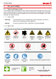
For your Safety 1. For your Safety 1.1 Terms and signs used In this manual and on the appliance itself, certain common terms and signs are used to warn you of possible dangers or to give you hints that are important in avoiding injury or damage. Observe and follow these hints and regulations to avoid accidents and damage. These terms and signs are explained below. 1.1.1 Terms used "Warning" is used whenever you or somebody else could be injured if you do not observe the accompanying safety regulation.
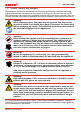
For your Safety 1.2 Product safety and dangers The appliances described in this manual are technically sophisticated, manufactured using high-quality materials and subject to many hours of testing in the factory. They contain the latest technology and comply with recognised technical safety regulations. However, there are still risks involved, even when the appliances are used as intended. These are described below. Warning! After removing covers, live parts may be exposed.
For your Safety 1.3 Requirements of the operating personnel The appliance may only be operated and maintained by persons who are of legal age and have been instructed accordingly. Personnel who are to be trained, instructed or who are undergoing general training may only work with the appliance under the continuous supervision of an experienced person. Repairs may only be performed by qualified electricians. The regulations in the separate service manual must be observed. 1.
For your Safety 1.7 Behaviour in case of malfunctions and irregularities The appliance may only be used in a flawless condition. If you as the operator notice irregularities, malfunctions or damage, immediately take the appliance out of service and inform your superior. You can find information on eliminating malfunctions from page 40. 1.8 What to do in case of accidents 1. Keep calm. Act with determination and consideration. Pay attention to your own safety. 2.
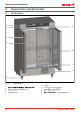
Construction and description 2. Construction and description 2.1 Construction 1 2 9 3 4 8 7 6 5 Fig.
Construction and description 2.2 Construction and function The appliance can heat up the interior to up to 50 °C and cool it down to +10 °C. A compressor is used for cooling. Humidification of the interior is achieved by evaporating water from a tank at a set rate by means of a hot-air generator on the rear side of the appliance. The sterile hot air is introduced into the interior above the fan and mixed with the air current.
Construction and description 2.5.2 Communication interfaces The communication interfaces are intended for appliances which meet the requirements of IEC 60950-1. USB interface The appliance is fitted by default with a USB interface in accordance with the USB specification. This way, you can ► transfer software stored on a USB storage medium to the appliance (see page 56). ► export protocol logs from the appliance to a USB storage medium (see page 60).
Construction and description 1 2 3 Typ: ICH 260 F.-Nr.: Y613.0088 230 V ~ 5.9 A 50/60 Hz 1350 W DIN12880-Kl.3.3 Nenntemp.: -10 - +60 °C 10 9 8 4 7 5 6 Fig. 5 Nameplate (example) 1 Type designation 2 Operating voltage 3 Applicable standard 4 Protection type 5 CE conformity 6 7 8 9 10 Address of manufacturer Disposal note Temperature range Connection / power ratings Appliance number 2.
Construction and description Appliance size 110 Adjustment range humidity (% rh) 260 10 to 80 Adjustment precision humidity (% rh) 1 CO2 adjustment range (%) 0 to 20 CO2 adjustment precision (%) CO2 variation in time (%) 750 0 to 10 0.1 at 0 to 10 % CO2 ±0.2 ±0.3 at 11 to 15 % CO2 ±0.5 – F 56 D E B C A Fig. 6 Dimensions 2.
Construction and description 2.10 Ambient conditions ► The appliance may only be used in enclosed areas and under the following ambient conditions: Ambient temperature 15 °C to 28 °C (to 34 °C with limited temperature and humidity range) Humidity rh max. 70 %, non-condensing Overvoltage category II Pollution degree 2 Altitude of installation max. 2,000 m above sea level ► The appliance may not be used in areas where there is a risk of explosion.
Delivery, transport and setting up 3. Delivery, transport and setting up 3.1 For your Safety Warning! Because of the heavy weight of the appliance, you could injure yourself if you try to lift it. For carrying appliances of size 110, at least 4 people are needed. Appliances larger than that may not be carried but must be transported with a manual pallet jack or forklift truck. 110 260 750 Warning! You may get your hands or feet squashed when transporting and installing the appliance.
Delivery, transport and setting up 3.2 Delivery The appliance is packed in cardboard and is delivered on a wooden palette. 3.3 Transport The appliance can be transported in three ways: ► With a forklift truck; move the forks of the truck entirely under the pallet. ► On a manual pallet jack ► On its own castors, in case of the corresponding configuration, for which the catch on the (front) castors must be released 3.
Delivery, transport and setting up 3.6 Setting up Warning! Due to its centre of gravity, the appliance can fall over to the front and injure you or other people. Always attach the appliance to a wall with the tilt protection (see page 19). In case there is not enough space, do not put the appliance into operation and do not open the door. Contact the Memmert service (see page 2). The appliance may only be installed on the floor. 3.6.
Delivery, transport and setting up 3.6.2 Tilt protection Attach the appliance to a wall with the tilt protection. The tilt protection is included in the delivery. 5. Screw the tilt protection as shown onto the back of the appliance. ≥ 20 cm 6. Bend the tilt protection upwards by 90 ° in the desired distance to the wall (consider the minimum distance to the wall, see Fig. 8). 7. Drill a hole, insert a plug and screw the tilt protection to a suitable wall.
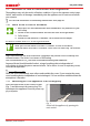
Putting into operation 4. Putting into operation Caution: The first time the appliance is operated, it must not be left unattended until it has reached the steady state. 4.1 Connecting the appliance Caution: Observe the country-specific regulations when making connections (e.g. in Germany DIN VDE 0100 with residual current circuit breaker). Observe the connection and power ratings (see nameplate and “Technical Data” on page 13). Make sure to establish a safe PE conductor connection. Fig.
Putting into operation Fill the supplied water tank with water and connect it with the enclosed tube to the “H2O” connection on the rear of the chamber (Fig. 10). For appliances of size 750, the tank can be attached to the appliance with the included tank holder (Fig. 11). To do so, hook the tank holder into the slots on the rear of the appliance. For wall mounting, the tank holder also has two drill holes (fastening material not included in the delivery). Fig.
Putting into operation 4.3 CO2 connection Warning! Danger of explosion and poisoning when introducing gases/materials other than CO2. Only carbon dioxide may be introduced into the appliance through the gas connection on the rear of the appliance. Warning! Danger of suffocation. CO2 can have a suffocating effect in high concentrations. In normal operation, the appliance emits small amounts of CO2 to its surroundings. You should therefore ensure that the room in which it is installed is properly ventilated.
Operation and control 5. Operation and control Warning! Danger of suffocation. CO2 can have a suffocating effect in high concentrations. In normal operation, the appliance emits small amounts of CO2 to its surroundings. You should therefore ensure that the room in which it is installed is properly ventilated. Always close the stop valve or pressure reducer on the gas bottle if the appliance is currently not in operation. Warning! High concentrations of CO2 can cause cold burns or frostbite.
Operation and control 5.1 Operating personnel The appliance may only be operated by persons who are of legal age and have been instructed accordingly. Personnel who are to be trained, instructed or who are undergoing general training may only work with the appliance under the continuous supervision of an experienced person. 5.2 Opening the door ► To open the door, pull the door handle to the side (to the left or to the right, depending Open / close the door on the door variation, see Fig. Fig. 14, A).
Operation and control 5.3 Loading the appliance Warning! When loading the appliance with an unsuitable load, poisonous or explosive vapours or gases may be produced. This could cause the appliance to explode, and people could be severely injured or poisoned. The appliance may only be loaded with materials which do not form any toxic or explosive vapours when heated up and cannot ignite (see also Intended use on page 8).
Operation and control 5.4 Operating the appliance 5.4.1 ControlCOCKPIT In manual operation, the desired parameters are entered at the ControlCOCKPIT on the front of the appliance (Fig. 16). You can also make basic settings here (menu mode). Additionally, warning messages are displayed, e.g. if the temperature is exceeded.
Operation and control 5.4.2 Basic operation In general, all settings are made according to the following pattern: 1. Activate the desired parameter (e.g. temperature). To do so, press the correspondHauptschalter ing activation key on the left or right of the respective display. The activated display is lined in colour, the other displays are dimmed. The set value is highlighted 344 40 in colour. TEMP TEMP 2237.4 °C Set100 .5°C .0 °C TIMER 100 % % Set 444.4 °C FAN TIMER Hauptschalter 02 10 0% 2.
Operation and control The status display shows you which operating mode or operating state the appliance is currently in. The current operating state is highlighted in colour and indicated by the text display: Appliance is in programme mode Programme is stopped Appliance is in manual mode The example on the right shows the appliance in manual mode, identified by the coloured hand symbol. ■ ► When the appliance is in timer mode, Timer active is displayed: 13:44 12.Sept.2012 Manual Mode 13:44 12.
Operation and control CO2 Adjustment range: 0 to 10 % or 0 to 20 % in steps of 0.1% (depends on appliance size) CO2 1.15.0 % 0% Set 5.4.5 Operation with digital backwards counter with target time setting, adjustable from 1 minute to 99 days (Timer) In timer operation, you can adjust the time the appliance runs at the set value. The appliance has to be in manual operating mode for this. 100 .5°C 1. Press the activation key to the left of Hauptschalter the timer display. The timer display is activated.
Operation and control When the timer has elapsed, the display shows 00h:00m. All functions (heating etc.) are switched off. In addition, an acoustic alarm sounds, which can be turned off by pressing the confirmation key. TIMER 00 00 h End To deactivate the timer, open the timer display by pressing the activation key again and then turning the turn control to reduce the timer setting until --:-- is displayed. Confirm with the confirmation key. m 13:30 23.11. TIMER -- -h End 5.4.
Operation and control You cannot change any parameters (e.g. the temperature) at the appliance while a programme is running. However, the displays ALARM and GRAPH can still be used. Cancelling a programme Hauptschalter You can cancel an active programme atLIGHT any time. 1. Press the activation key to the right of the status display. The status display is 344 40 automatically highlighted. ALARM 100 % TEMP % FAN TIMER 02 10 d h 2. Turn the turn control until the UF 110 symbol is highlighted.
Operation and control 5.5 Monitoring function 5.5.1 Temperature monitoring The appliance is equipped with a multiple overtemperature protection in accordance with DIN 12 880.
Operation and control Electronic temperature monitoring ((TWW) TWW) The manually set monitoring temperature min and max of the overtemperature control is monitored by an adjustable over/undertemperature controller (TWW) protection class 3.3 acc. to DIN 12 880. If the manually set monitoring temperature max is exceeded, the TWW takes over temperature control and begins to regulate the monitoring temperature (Fig. 18). °C Emergency operation Setting MAX Set temperature Controller error t Fig.
MP Operation and control Automatic temperature monitor ((ASF) ASF) ASF is a monitoring device that automatically follows the set temperature setpoint within an adjustable tolerance band (Fig. 19). The ASF – if switched on – is automatically activated as soon as the actual temperature value reaches 50 % of the set tolerance band of the setpoint (in the example: 50 °C ± 1 K) for the first time (section A). When the temperature violates the set tolerance band around the setpoint (in the example in Fig.
TEMP FLAP 344.4 °C 40 % Set 444.4 °C FAN TIMER 02 10 d 0% h End 29 Sept. 22 24 Hauptschalter 100 % min auto max 444.4 °C +/- 0.0 K 2. Save the selection UF 110 by pressing the confirmation key. The min setting (undertemperature protection) is automatically > activated. Zu der Typenbezeichnung344 gibt es momentan drei40 Entwurfsrichtungen, PLUS ALARM min max 15 .0 °C ON O N TEMP FLAP .4 °C 44.Sept 100auto % 02 10 d Hauptschalter 0% h End 29 Sept. 22 24 3.
MP TEMP FLAP 344.4 °C Operation and control Hauptschalter 40 % Set 444.4 °C FAN TIMER 02 10 d h End 29 Sept. 22 24 0% +/- 0.0 K 35 100.5 °C % FAN 38 .5 °C Manu auto Zu der Typenbezeichnung gibt es momentan drei Entwurfsrichtungen, ich kann Ihnen noch nichtdsagen,hob Memmert hierzu % schon eine Entscheidung End 29 Sept. 22 24 getroffen hat. Die hier gezeigt Variante, ist die von uns empfohlene Richtung. 0 02 10 max 44.Sept % Set 444.4 °C TIMER ALARM min FLAP .4 °C 444.
CO2 TEMP 344.4 °C FAN TIMER 02 10 d 44.Sept 40 % Set 444.4 °C Hauptschalter auto GAS 100 ALARM +/- 4.4 K min Operation andmax control FLAP 0% h End 29 Sept. 22 24 TEMP FLAP 444.4 °C CO2 min GAS 44 .4 %rh 100 min ON O N d FLAP 44.Sept 40 ALARM 444.4 °C auto 344.4 °C ALARM 40 % 100 CO 2 min min % GAS CO 2 GAS Manu max max 70 44.0.4%rh %rh CO CO 22 GAS .4 %rh 50.044444 %rh 444 0 02 10 CO2 max 44.Sept > Set 444.
MP Operation and control TEMP FLAP 44180.0 °C 40 .4 °CSetting CO2 monitoring % Set 444.4 °C Set 999.9 °C ON 1. Press the activation key to the left of the FAN FLAP ALARM display. The temperature monitoring setting d h 2 10 20%% is automatically activated. 4h:44m MER ER 29 14Sept. : 45 22 24 aufheizen 09:12h Hauptschalter ALARM ALARM max min min max max 0 TEMP 344.4 °C Hauptschalter 40 % FAN TIMER 02 10 d 444 15.4.0°C°C 000°C minauto auto FLAP Set 444.4 °C 0% h End 29 Sept.
Operation and control 5.6 Graph The GRAPH display provides an overview of the chronological sequence of the setpoint values and actual values for temperature, humidity and CO2 content as a curve. 5.6.1 Temperature profile Press the activation key to the right of the GRAPH display. The display is enlarged and the temperature profile shown. et 444.4 °C 12.09.2012 Fr 20.10.2010 20:34 80 39 60 40 38 20 0 4 14.00 ► To display the setpoint and 8 16.00 12 16 2018.
Malfunctions, warning and error messages 6. Malfunctions, warning and error messages Warning! After removing covers, live parts may be exposed. You may receive an electric shock if you touch these parts. Malfunctions requiring work inside the appliance may only be rectified by electricians. ObHauptschalter serve the separate service manual for this. Do not try to rectify appliance errors yourself but contact the MEMMERT customer service department (see page 2) or an authorised service point.
Malfunctions, warning and error messages Description Cause Action Appliance does not heat up any more The mechanical temperature limiter (TB) permanently switched off heating. 1. Wait until the appliance cools down. 2. Reset the TB. To do so, press the red button on the right of the appliance rear side until a clicking sound can be heard: See If the alarm continues: Contact page 2 customer service 6.1.
Malfunctions, warning and error messages 6.1.3 CO2 monitoring Description Cause Alarm display upper CO2 alarm limit exceeded Action See Open the door for 30 sec. and wait to see if the appliance then steadily adjusts to the setpoint. If the error occurs again, contact customer service. CO2 13.0 % page 2 Set 10.0 % Alarm display value below lower CO2 alarm limit Check if the door is closed. Check the correct connection, valve and level of the gas bottle. If necessary, connect a new gas bottle.
Malfunctions, warning and error messages Description Cause Action Error message AI E-3 in the temperature display Temperature monitoring sensor defective. The operating sensor takes over the measurement function. ► The appliance can Operating and monitoring sensor defective ► Switch off appli- TEMP 37.4 °C temporarily be kept in service ► Contact customer service as soon as possible See page 2 AI E-3 Set 37.
Malfunctions, warning and error messages 6.3 Power failure In case of a power failure, the appliance operates as follows: In manual mode After power supply has been restored, operation is continued with the parameters set. The time and duration of the power failure are documented in the log memory. In timer or programme mode In case of an interruption of the power supply of less than 60 minutes, the current programme is continued from the point at which it was interrupted.
Menu mode 7. Menu mode In menu mode, you can make basic settings, load programmes and export protocols, as well as adjust appliance parameters. Hauptschalter Caution: Before changing menu settings, read the description of the respective functions on the following pages to avoid possible damage to the appliance and/or chamber load. To enter menu mode, press the MENU key. To exit the menu mode at any time, press the 344 .4 °CMENU key 40 % again. The appliance then returns to manual mode.
Menu mode 7.2 Basic operation in menu mode using the example of language selection In general, all settings in menu mode are done just like in manual mode: Activate the respective display, use the turn control for setting and press the confirmation key to accept the change. A more detailed description is provided in the following, using the example of language selection. 1. Activate the desired parameter (in this example the language).
Menu mode All other settings can be made accordingly. The settings possible are described in the following sections. If no new values are entered or confirmed for approx. 30 seconds, the appliance automatically returns to the main menu and restores the former values. 7.3 Setup 7.3.
Menu mode 1. Activate Hauptschalter the SETUP display. The entry IP address is automatically highlighted. TEMP 344.4 °C FLAP 40 % Set 444.4 °C FAN TIMER 02 10 d Hauptschalter SETUP IP address Balance Subnet mask IP Adresse 0% h End 29 Sept. 22 24 2. Accept the selection UF 110 by pressing the confirmation key. The first three digits of the IP address are automatically selected. Unit Einheit Alarm AlarmTemp Temp °C TWW F TWB 44.
Menu mode 7.3.4 Timer mode SETUP IP address 255. 145. 1 3 6 . 225 Subnet mask 255. 255. 0 . 0 Unit Alarm temp Timer mode Slide-in unit °C F TWW TWB Grid Shelf tTimer A B tTimer 6K °C/°F Here, you can choose whether the digital backwards counter with target time setting (see page 29) should run setpointdependent or not. This determines whether the timer should not start until a tolerance band of ±3 K around the set temperature is reached (Fig.
Menu mode If humidity/room temperature are particularly high, it is possible that the factory setting for defrosting, 12 hours, is not sufficient. If this is the case, you should set a more frequent defrosting interval, e.g. every 6 hours. Automatic defrosting is disabled with the setting Off. When operating at low temperatures, this over time causes the cooling unit to ice over. Regular defrosting needs to be carried out in order to prevent damage to the cooling system. Setup 7.3.
TEMP FLAP 344.4 °C 40 % Set 444.4 °C Hauptschalter FAN TIMER 02 10 d 0% h 2. Turn the turn control until Time zone is highlighted. UF 110 End 29 Sept. 22 24 PLUS TEMP 344.4 °C ON O N FLAP 40 % Set 444.4 °C > FAN TIMER Zu der Typenbezeichnung gibt es momentan drei Entwurfsrichtungen, % d h ich kann Ihnen noch nicht sagen, ob Memmert hierzu schon eine Entscheidung End 29 Sept. 22 24 getroffen hat. Hauptschalter Die hier gezeigt Variante, ist die von uns empfohlene Richtung. 0 02 10 3.
Menu mode 7.5 Calibration To guarantee perfect control, we recommend to calibrate the appliance once a year. 7.5.1 Temperature adjustment The appliances are temperature calibrated and adjusted at the factory.
TEMP 344.4 °C FLAP 40 % Set 444.4 °C Hauptschalter FAN TIMER 02 10 d 0% h End 29 Sept. 22 24 3. With the turn control, set the calibration temperature Cal2 UF 110to 30 °C. PLUS TEMP 344.4 °C ON O N 100 % FLAP min ALARM 444.4 °C - 0,2 K +0,1 K - 0,2 K 5.0 C Cal1 44.Sept 100 % 30.0 C Cal2 Manu 0 4. Save the setting by pressing the confirUF 110 mation key. The corresponding calibration value is automatically highlighted. Menu mode JUSTIEREN max +/- 0.
Menu mode 7.5.2 Humidity calibration Humidity control can be adjusted according to customer requirements by means of three freely selectable balance points. For each selected calibration point, a positive or negative compensation correction value between –10 % and +10 % can be set (Fig. 28). For humidity adjustment, you will need a calibrated reference measuring device. rh 90 -1,5 % rh 50 +1,5 % rh 20 +3,0 % r to Fac 20% 0% Fig.
TEMP 344.4 °C FLAP 40 % Set 444.4 °C FAN TIMER 02 10 d 0% h End 29 Sept. 22 24 Hauptschalter 100 % ALARM min 444.4 °C auto 44.Sept Manu Menu mode max 444.4 °C +/- 0.0 K JUSTIEREN 5. Save the setting by pressing the confirUF 110 mation key. The corresponding calibration value is automatically highlighted. PLUS Temperature Cal1 10.0 %rh - 0,5 % Humidity Cal2 60.0 %rh +1,0 % ON O N TEMP FLAP CO2 > °C % Zu der Typenbezeichnung gibt es.4momentan drei Entwurfsrichtungen, Set 444.
Menu mode 7.5.3 CO2 calibration The CO2 control can be calibrated according to customer requirements by means of three freely selectable balance points. For each selected balance point, a positive or negative compensation correction value can be set (Fig. 29). For CO2 calibration, a calibrated CO2 measuring instrument is required. Cal3 -0,7 % Cal2 +1,5 % Cal1 -0,4 % to Fac 10% 0% Fig. 29 tion bra ali ry c 20% CO2 calibration (example) Example: CO2 deviation at 10 % has to be corrected: 1.
TEMP 344.4 °C FLAP 40 % Set 444.4 °C FAN TIMER 02 10 d 0% h End 29 Sept. 22 24 Hauptschalter 100 % ALARM min 444.4 °C auto 44.Sept Manu Menu mode max 444.4 °C +/- 0.0 K JUSTIEREN 5. Save the setting by pressing the confirUF 110 mation key. The corresponding calibration value is automatically selected. PLUS Temperature Cal1 5.0 %CO2 - 0,5 % Humidity Cal2 10.0 %CO2 +1,0 % CO2 Cal3 15.0 %CO2 +1,0 % ON O N TEMP FLAP > °C % Zu der Typenbezeichnung gibt es.
Menu mode 7.6 Program In the PROG display, programmes created using the AtmoCONTROL software can be transferred to the appliance and saved on a USB storage medium. Here, programme to be used in manual mode can also be selected (see page 32) and programmes can be deleted. To load a programme from a USB storage medium: Connect the USB storage medium with the saved programme(s) to the interface on the right side of the control panel. LANGUAGE SETUP 1. Activate the programme display.
Menu mode 7.7 Sound In the Sound display, it can be define whether or not the appliance should emit acoustic signals and, if yes, on which events: ► on the press of a key ► at the end of a programme ► on alarm ► if the door is open 1. Activate the acoustic signal adjustment. To do so, press the activation key on the left side of the SOUND display. The Hauptschalter display is enlarged. The first category (in this case Key sound) is automatically highlighted. On the right, the current settings are shown on.
SOUND ATION Menu mode 7.8 Protocol The appliance continually logs all relevant measured values, settings and error messages at 1-minute intervals. The internal log memory is of the continuous memory type. The logging function cannot be switched off and is always active. The measured data are stored in the appliance, safe from manipulation. If the power supply is interrupted, the time of the power failure and voltage recovery are stored in the appliance.
E P Menu mode 7.9 User-ID 7.9.1 Description With the User-ID function, you can lock the settings of individual (e.g. temperature) or all parameters, so that they cannot be changed at the appliance by accident or unauthorised persons. You can also lock setting options in menu mode (e.g. adjustment or date and time settings) this way. If adjustment options are locked, this is indicated TEMP by the lock symbol in the respective display (Fig. 30).
Maintenance and Servicing 8. Maintenance and Servicing Warning! Danger due to electric shock. Before doing any maintenance work, pull out the mains plug. Warning! In case of appliances of a certain size, you can get accidentally locked in, which is life-threatening. Do not climb into the appliance! Caution! Danger of cuts due to sharp edges. Always wear gloves when working in the chamber interior. 8.
Maintenance and Servicing 8.2.4 Cooling unit In order to guarantee perfect function and a long lifetime of the refrigeration unit, it is absolutely essential to remove dust deposits from the condenser (with a vacuum cleaner, paintbrush or bottle brush, depending on the amount of dust). To do so, open the screws at the lower front cover (number varies depending on the appliance size) and remove the front cover (Fig. 31). Fig. 31 Unscrew and remove the front cover 8.2.
Storage and disposal 9. Storage and disposal 9.1 Storage The appliance may only be stored under the following conditions: ► in a dry and enclosed, dust-free room ► frost-free ► disconnected from the power supply and gas supply Close the valve of the gas bottle and disconnect the gas bottle. Gas bottles may only be stored in closed rooms if these are sufficiently well ventilated. Before storage, remove water tube and empty the water tank (see page 21). 9.
Index Index A E M Accessories 15 Accidents 9 Activation key 27 Alarm 32, 34, 36, 40 Ambient conditions 15 Ambient temperature 15 Appliance error 42 ASF 32, 34 AtmoCONTROL 3, 12, 15, 27, 30, 58, 60, 61 Electrical connection 11 Electrical equipment 11 Electronic temperature monitoring 33 Emergency 9 Ending operation 39 End of programme 31 Error messages 40 Ethernet 12 Maintenance 62 Malfunctions 9, 40, 42 Manufacturer 2 Material 11 Mechanical temperature monitoring 34 Menu 50 Minimum clearances 18 Monit
Index S T U Safety regulations 6, 10 Service 63 Servicing 63 Setting parameters 46 Setting up 16, 18 Setup 47 Shelf 49 Slide-in unit 49 Speaker symbol 32, 36, 40 Standards 14 Storage after delivery 17 Switching off 39 Switching on 22 Tank holder 21 TB 34 Technical data 13 Temperature 28 Temperature adjustment 52 Temperature comparison 52 Temperature deviation 52 Temperature limiter 34 Temperature monitor 32, 34 Temperature monitoring 31, 32 Temperature profile 39 Temperature sensor 32 Tilt protection 1
Climate chamber ICH D30393 | Date 10/2014 englisch Memmert GmbH + Co. KG Willi-Memmert-Straße 90-96 | D-91186 Büchenbach Tel. +49 9122 925-0 | Fax +49 9122 14585 E-Mail: sales@memmert.com facebook.com/memmert.family Die Experten-Plattform: www.atmosafe.