
Manual


63
Advanced Functions
Setting
Setting
1.
Set the desired CO
2
balance point in the SETUP (
see page
53
)
and set the accompanying
compensation correction value to
0.0 %.
2.
With a reference instrument, measure the deviation in the stationary state in the selected
CO
2
balance point.
3.
Under SETUP, adjust the compensation correction value. If the measured reference CO
2
content is too low, the compensation correction value must be set with a negative sign.
4.
Perform a control measurement with the reference instrument.
5.
The procedure can be performed for the CO
2
balance points 5 %, 10 % and 15 %.
Example: CO
2
deviation at 10 % should be corrected:
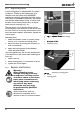
1.
Set the CO
2
balance point in the SETUP to
CO2 10
and set the accompanying compensation
correction value to
0.0 %:
PRINT
SETUP
loop
t3
t4
t2
t1
on
off
Mo
Tu
We
Th
Fr
Sa Su
3
4
2
1
STERI DEFRO
°C
°C
rh
mb
%
CO
mb
2
IN 1
IN 2
OUT
IN 1
IN 2
OUT
MIN
AUTO
MAX
2.
With a calibrated reference instrument and at a defined setpoint CO
2
content of
10.0 %,
an
actual CO
2
content of 11.5 % is measured.
3.
Set the compensation correction value in the SETUP for
CO2 10
to
1.5 %:
PRINT
SETUP
loop
t3
t4
t2
t1
on
off
Mo
Tu
We
Th
Fr
Sa Su
3
4
2
1
STERI DEFRO
°C
°C
rh
mb
%
CO
mb
2
IN 1
IN 2
OUT
IN 1
IN 2
OUT
MIN
AUTO
MAX
4.
The reference instrument should display 10 % after the calibration procedure.
With
CO2 5
and
CO2 15
, further calibrations can be programmed at 5 % and 15 %.
If all compensation correction values are set to
0.0
%
, the factory CO
2
calibration
settings are restored.