HPP IPP OPERATING INSTRUCTIONS CONSTANT CLIMATE CHAMBER HPP COOLED INCUBATOR IP IPPPLUS 100% ATMOSAFE. MADE IN GERMANY. www.memmert.com | www.atmosafe.
Manufacturer and customer service Memmert GmbH + Co. KG Willi Memmert Straße 90-96 D-91186 Büchenbach Deutschland Phone: +49 (0)9122 925-0 Fax: +49 (0)9122 14585 E-mail: sales@memmert.com Internet: www.memmert.com Customer service: Service hotline: +49 (0)9171 9792 911 Service fax: +49 (0)9171 9792 979 E-mail: service@memmert.com When contacting customer service, always quote the product serial number on the nameplate (see page 13). Shipping address for repairs: Memmert GmbH + Co.
About this manual About this manual Purpose and target group This manual describes the assembly, function, transport and operation of constant climate chambers HPP and cooled incubators IPPPLUS. It is intended for use by trained personnel of the owner, who have the task of operating and/or maintaining the respective appliance. If you are asked to work on the appliance, read this manual carefully before starting. Familiarise yourself with the safety regulations.
Contents Contents 1. For your Safety 1.1 1.2 1.3 1.4 1.5 1.6 1.7 1.8 Terms and signs used........................................................................................................... 6 Product safety and dangers ................................................................................................ 7 Requirements of the operating personnel .......................................................................... 7 Responsibility of the owner.......................................
Contents 7. Menu mode 7.1 7.2 7.3 7.4 7.5 7.6 7.7 7.8 7.9 Overview ............................................................................................................................ 43 Basic operation in menu mode using the example of language selection....................... 44 Setup.................................................................................................................................. 45 Date and Time .................................................................
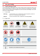
For your Safety 1. For your Safety 1.1 Terms and signs used In this manual and on the appliance itself, certain common terms and signs are used to warn you of possible dangers or to give you hints that are important in avoiding injury or damage. Observe and follow these hints and regulations to avoid accidents and damage. These terms and signs are explained below. 1.1.1 Terms used "Warning" is used whenever you or somebody else could be injured if you do not observe the accompanying safety regulation.
For your Safety 1.2 Product safety and dangers The appliances described in this manual are technically sophisticated, manufactured using high-quality materials and subject to many hours of testing in the factory. They contain the latest technology and comply with recognised technical safety regulations. However, there are still risks involved, even when the appliances are used as intended. These are described below. Warning! After removing covers, live parts may be exposed.
For your Safety ► has to ensure that the appliance and its surroundings are kept clean and tidy, for example through corresponding instructions and inspections; ► is responsible for ensuring that personal protective clothing is worn by operating personnel, e.g. work clothes, safety shoes and protective gloves. 1.
Construction and description 2. Construction and description 2.1 Construction 1 9 8 2 1 3 7 4 5 Fig.
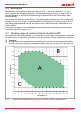
Construction and description 2.2 Description The appliance can heat the working chamber up to 70 ºC and cool it down to 5 ºC. Lownoise, long-life and energy-saving Peltier cooling and heating technology is used for this. In heating operation, a part of the required energy is extracted from the surroundings (heat pump principle). Additionally, the humidity in the interior of constant climate chambers HPP can be regulated between 10 and 90 % rh (rh = relative humidity).
Construction and description Range A: In this range, temperature and humidity can be combined as you please, without resulting in any significant condensation. If there are extreme ambient conditions, the working range may be restricted. Range B: If the specified range is exceeded upwards, e.g. 80 % rh at 60°C, the hot steam fed in will immediately condense, due to the dew-point, at the coldest point in the appliance.
Construction and description 2.6.2 Communication interfaces The interfaces are intended for appliances which meet the requirements of IEC 60950-1. USB interface The appliance is fitted by default with a USB interface in accordance with the USB specification. This way, you can ► transfer software stored on a USB storage medium to the appliance (see page 55). ► export protocol logs from the appliance to a USB storage medium (see page Fig. 4 USB interface 57).
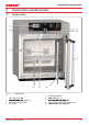
Construction and description 2.7 Designation (nameplate) The nameplate (Fig. 6) provides information about the appliance model, manufacturer and technical data. It is attached to the front of the appliance, on the right behind the door (see page 9). 1 2 3 Typ: HPP 260 230 V ~ DIN12880-Kl.3.1 F.-Nr.: 0109.0088 2.3 A 50/60 Hz 525 W Nenntemp.: 70 °C 10 9 8 4 7 5 6 Fig.
Construction and description 2.8 Technical data Appliance size 30 55 110 260 750 Appliance width D1 [mm] Appliance height E1 [mm] Appliance depth G1 (footprint) [mm] Depth of door lock [mm] Appliance depth F1 (including door handle) [mm] Working chamber width A1 [mm] Working chamber height B1 [mm] Working chamber depth C1 [mm] Chamber volume [litres] Weight [kg] Power [W] 230 V, 50/60 Hz Current consumption [A] 115 V, 50/60 Hz max. number of sliding shelves max.
Construction and description 2.9 Applied directives and standards ► Directive 2004/108/EC amended (Directive of the council on harmonisation of the laws of the member states on electromagnetic compatibility). Fulfilled standards: DIN EN 61326:2004-05, EN 61326:1997, EN 61326/A1:1998, EN 61326/A2:2001 EN 61326/A2:2003 ► Directive 2006/95/EC amended (Directive of the council on harmonisation of the laws of member states relating to electrical equipment designed for use within certain voltage limits).
Construction and description 2.12 Scope of delivery ► Power cable ► Tilt protection ► Sliding grid (load capacity 30 kg each) ► USB storage medium with software and AtmoCONTROL manual ► The operating instructions at hand ► Calibration certificate In addition for constant climate chambers HPP ► Water tank with connection hose ► Tank holder (only for appliances of size 750, see page 21) 2.13 Optional accessories ► Converter USB to Ethernet (Fig. 8).
Delivery, transport and setting up 3. Delivery, transport and setting up 3.1 Safety regulations Warning! Because of the heavy weight of the appliance, you could injure yourself if you try to lift it. To carry appliances of the sizes 30 and 55, at least two persons, for appliances of the sizes 110 and 260, four persons are needed. Appliances larger than that may not be carried but must be transported with a manual pallet jack or forklift truck.
Delivery, transport and setting up 3.2 Delivery The appliance is packed in cardboard and is delivered on a wooden palette. 3.3 Transport The appliance can be transported in three ways: ► With a forklift truck; move the forks of the truck entirely under the pallet ► On a manual pallet jack ► On its own castors, in case of the corresponding configuration, for which the catch on the (front) castors must be released 3.
Delivery, transport and setting up 3.6 Setting up Warning! Due to its centre of gravity, the appliance can fall over to the front and injure you or other people. Always attach the appliance to a wall with the tilt protection (see page 21). If this cannot be done due to space problems, do not operate the appliance and do not open the door. Contact the Memmert service team (see page 2). 3.6.
Delivery, transport and setting up 3.6.2 Installation options Setting up Comments Suitable for appliance size ... 30 55 110 260 750 Check the load capacity first two appliances maximum; mounting material (feet) provided Separately packaged fastening material is included in the scope of delivery. Observe the assembly instructions provided.
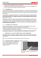
Delivery, transport and setting up 3.6.3 Tilt protection Attach the appliance to a wall with the tilt protection. The tilt protection is included in the delivery. 1. As illustrated, fasten the tilt protection to the rear side of the appliance. ≥ 20 cm 2. Bend the tilt protection upwards by 90 ° in the desired distance to the wall (consider the minimum distance to the wall, see Fig. 9). 3. Drill a hole, insert a plug and screw the tilt protection to a suitable wall.
Putting into operation 4. Putting into operation Caution: The first time the appliance is operated, it must not be left unattended until it has reached the steady state. 4.1 Connecting the appliance Caution: Observe the country-specific regulations when making connections (e.g. in Germany DIN VDE 0100 with residual current circuit breaker). Observe the connection and power ratings (see nameplate and Technical data on page 14). Make sure to establish a safe PE conductor connection. Fig.
Putting into operation Fill the supplied water tank with water and connect it with the enclosed tube to the „H2O“ connection on the rear of the chamber (Fig. 11). For appliances of size 750, the tank can be attached to the appliance with the included tank holder (Fig. 12). To do so, hook the tank holder into the slots on the rear of the appliance. For wall mounting, the tank holder also has two drill holes (fastening material not included in the delivery). Hauptschalter Fig. 11 Water connection Fig.
Operation and control 5. Operation and control 5.1 Operating personnel The appliance may only be operated by persons who are of legal age and have been instructed accordingly. Personnel who are to be trained, instructed or who are undergoing general training may only work with the appliance under the continuous supervision of an experienced person. 5.2 Opening the door ► To open the door, pull the handle bar to the side (to the left or to the right, depending on the door variation, Fig. 14, A).
Operation and control 5.3 Loading the appliance Warning! When loading the appliance with an unsuitable load, poisonous or explosive vapours or gases may be produced. This could cause the appliance to explode, and people could be severely injured or poisoned. The appliance may only be loaded with materials which do not form any toxic or explosive vapours when heated up and cannot ignite (see also Intended use on page 8).
Operation Hauptschalter 1 and control 2 TEMP TEMP TEMP 3 11 FLAP FLAP TEMP LIGHT LIGHT 344 22.4.4.4°C°C°C22.4 °C 40 %% 100%%% ON100 Set 4 Set 444 .4°C °C Set444 37..0 °C Set 37.0 °C FAN FAN HUMIDITY TIMER TIMER TIMER ALARM ALARM ALARM of °C max min max min min max max 30.00%rh%% 02 10 04 30 44 :44 dd hh m h End 29 Sept. 24 End 2923.Nov Sept. 22 24 End 13:30 End 14: 45 22 12 444 444 °C 35.4.4.5°C °C 000°C minauto auto auto Set 30.0 %rh 444 444 .4°C °C 38 .5 °C.4 000°C off +//-0.0 0.
Operation and control 5.4.2 Basic operation In general, all settings are made according to the following pattern: 1. Activate the desired parameter (e.g. temperature). To do so, press the correspondHauptschalter ing activation key on the left or right or the respective display. The activated display is lined in colour, the other displays are dimmed. The set value is highlighted 344 40 in colour. TEMP TEMP 2222.4 °C 100 .5°C 100 % % Set 444.4 °C Hauptschalter FAN TIMER 02 10 0% 2.
Operation and control The status display shows you which operating mode or operating state the appliance is currently in. The current operating state is highlighted in colour and indicated by the text display: Appliance is in programme mode 12.Sept.2012 13:44 Programme is stopped Appliance is in manual operating mode Manual Mode The example on the right shows the appliance in manual mode, identified by the coloured hand symbol.
Operation and control The interior light is only active at temperatures of up to 40 °C. If this temperature is exceeded, the interior light switches off automatically. The light display will then show “Temp too high”. LIGHT 0% Temp too high 5.4.5 Operation with digital backwards counter with target time setting, adjustable from 1 minute to 99 days (Timer) In timer operation, you can adjust the time the appliance runs at the set value. The appliance has to be in manual operating mode for this. 100 .
Operation and control When the timer has elapsed, the display shows 00h:00m. All functions (heating etc.) are switched off. In addition, an acoustic alarm sounds, which can be turned off by pressing the confirmation key. TIMER 00 00 h End To deactivate the timer, open the timer display by pressing the activation key again and then turning the turn control to reduce the timer setting until --:-- is displayed. Confirm with the confirmation key. m 13:30 23.11. TIMER -- -h End 5.4.
Operation and control Cancelling a programme Hauptschalter You can cancel an active programme atLIGHT any time. 1. Press the activation key to the right of the status display. The status display is 344 40 automatically highlighted. ALARM 100 % TEMP % FAN TIMER 02 10 d h 2. Turn the turn control until the UF 110 symbol is highlighted. PLUS TEMP 344 0% min End 29 Sept. 22 24 ON O N Test 012 Betrieb manueller Ramp 3 FLAP .4 °C stop ■100°C 100 % APH GRAPH Set 444.
Operation and control 5.5 Monitoring function 5.5.1 Temperature monitoring The appliance is equipped with a multiple overtemperature protection in accordance with DIN 12 880.
Operation and control Electronic temperature monitoring ((TWW) TWW) The manually set monitoring temperature min and max of the overtemperature control is monitored by an adjustable over/undertemperature controller (TWW) protection class 3.3 acc. to DIN 12 880. If the manually set monitoring temperature max is exceeded, the TWW takes over temperature control and begins to regulate the monitoring temperature (Fig. 19). °C Emergency operation Setting MAX Set temperature Controller error t Fig.
MP Operation and control Automatic temperature monitor ((ASF) ASF) ASF is a monitoring device that automatically follows the set temperature setpoint within an adjustable tolerance band (Fig. 20). The ASF – if switched on – is automatically activated as soon as the actual temperature value reaches 50 % of the set tolerance band of the setpoint (in the example: 50 °C ± 1 K) for the first time (section A). When the temperature violates the set tolerance band around the setpoint (in the example in Fig.
TEMP FLAP 344.4 °C 40 % Set 444.4 °C FAN TIMER 02 10 d 0% h End 29 Sept. 22 24 Hauptschalter 100 % min auto max 444.4 °C +/- 0.0 K Save the selectionUFby 110pressing the confirmation key. The min setting (undertemperature protection) is automatically activated. PLUS ALARM min max 15 .0 °C ON O N TEMP FLAP > °C % Zu der Typenbezeichnung gibt es .4 momentan drei Entwurfsrichtungen, Set 444.4 °C ich kann Ihnen noch nicht sagen, ob Memmert hierzu schon eine Entscheidung getroffen hat.
MP TEMP FLAP 344.4 °C Operation and control Hauptschalter 40 % Set 444.4 °C FAN TIMER 02 10 d 0% h End 29 Sept. 22 24 +/- 0.0 K 35 100.5 °C % FAN 38 .5 °C Manu auto Zu der Typenbezeichnung gibt es momentan drei Entwurfsrichtungen, ich kann Ihnen noch nichtdsagen,hob Memmert hierzu % schon eine Entscheidung End 29 Sept. 22 24 getroffen hat. Die hier gezeigt Variante, ist die von uns empfohlene Richtung. 0 02 10 max 44.Sept % Set 444.4 °C TIMER ALARM min FLAP .4 °C 444.
4.4 °C et 444.4 °C TEMP FAN TIMER 02 10 d 44.Sept 40 % Set 444.4 °C Hauptschalter ALARM ALARM 100min % max min max FLAP 344.4 °C Manu 0% h End 29 Sept. 22 24 min auto PLUS TEMP FLAP 344.4 °C max 444.4 °C +/- 0.0 K min ALARM 444.4 °C 444.4 °C max CO2 444.4 °C auto +/- 0.0 K GAS 5. Accept the selection UF 110 by pressing the confirmation key. The upper humidity alarm limit is automatically highlighted. PLUS auto ALARM ON O N TEMP CO2 min 100 % GAS 44 50.4.
40 % 4.4 °C Set 444.4 °C TEMP FLAP 344.4 °C Operation and control 40 % Set 444.4 °C FAN TIMER 02 10 d ► To extend or reduce the time h End 29 Sept. 22 24 100 0% ALARM min 444.4 °C auto max 444 +/- 0 Fr 20.10.2010 20:34 °C UF 110 frame to be displayed: Press12.09.2012 the activation 100 key next to the 80 magnifying glass symbol.
Malfunctions, warning and error messages 6. Malfunctions, warning and error messages Warning! After removing covers, live parts may be exposed. You may receive an electric shock if you touch these parts. Malfunctions requiring work inside the appliance may only be rectified by electricians. Observe the separate service manual for this. Hauptschalter Do not try to rectify appliance errors yourself but contact the MEMMERT customer service department (see page 2) or an authorised service point.
Malfunctions, warning and error messages 6.1.2 Humidity monitoring (for constant climate chambers HPP only) Description Cause Action See Error symbol Water tank empty Fill the water tank with demineralised/distilled water and press the confirmation key page 22 Upper humidity limit exceeded Open the door for 30 sec. and wait to see if the appliance reliably adjusts to the setpoint. If the error occurs again, contact customer service. HUMIDITY 55.4 %rh Set 55 .
Malfunctions, warning and error messages Error description Cause of error Rectifying errors Display T:E-3 in the temperature display Temperature operating sensor defective. The monitoring sensor takes over the measurement function. ► The appliance can TEMP 37.4 °C T:E-3 Set 37.0 °C Error message AI E-3 in the temperature display TEMP 37.4 °C Temperature monitoring sensor defective. The operating sensor takes over the measurement function.
Malfunctions, warning and error messages 6.3 Power failure In case of a power failure, the appliance operates as follows: In manual mode After power supply has been restored, operation is continued with the parameters set. The time and duration of the power failure are documented in the log memory. In timer or programme mode In case of an interruption of the power supply of less than 60 minutes, the current programme is continued from the point at which it was interrupted.
Menu mode 7. Menu mode In menu mode, you can make basic settings, load programmes and export protocols, as well as adjust appliance parameters. Hauptschalter Caution: Before changing menu settings, read the description of the respective functions on the following pages to avoid possible damage to the appliance and/or chamber load. To enter menu mode, press the MENU key. To exit the menu mode at any time, press the 344 .4 °CMENU key 40 % again. The appliance then returns to manual mode.
Menu mode 7.2 Basic operation in menu mode using the example of language selection In general, all settings in menu mode are done just like in manual mode: Activate the respective display, use the turn control for setting and press the confirmation key to accept the change. A more detailed description is provided in the following, using the example of language selection. 1. Activate the desired parameter (in this example the language).
Menu mode All other settings can be made accordingly. The settings possible are described in the following sections. If no new values are entered or confirmed for approx. 30 seconds, the appliance automatically returns to the main menu and restores the former values. 7.3 Setup 7.3.
Menu mode 1. Activate Hauptschalter the SETUP display. The entry IP address is automatically highlighted. TEMP 344.4 °C FLAP 40 % Set 444.4 °C FAN TIMER 02 10 d Hauptschalter SETUP IP address Balance Subnet mask IP Adresse 0% h End 29 Sept. 22 24 2. Accept the selection UF 110 by pressing the confirmation key. The first three digits of the IP address are automatically selected. Unit Einheit Alarm AlarmTemp Temp °C TWW F TWB 44.
Menu mode 7.3.4 Timer mode SETUP IP address 255. 145. 1 3 6 . 225 Subnet mask 255. 255. 0 . 0 Unit Alarm temp Timer mode Slide-in unit °C F TWW TWB Grid Shelf tTimer A B tTimer 6K °C/°F Here, you can choose whether the digital backwards counter with target time setting (see page 29) should run setpoint-dependent or not. This determines whether the timer should not start until a tolerance band of ±3 K around the set temperature is reached (Fig.
Menu mode 7.3.6 Balance (only for model sizes 260 and 750) For appliances of the sizes 260 and 750, application-specific correction of the heat output distribution (balance) between the upper and lower heating groups is possible. The adjustment range is from –50 % to +50 %. upper heat output upper heat output lower heat output lower heat output +30% -20% SETUP 2/2 Balance SETUP 2/2 -20 % Balance +30 % Fig.
Menu mode 7.3.8 Gateway The setup entry Gateway is used to connect two networks with different protocols. The gateway is set the same way as the IP address (see page 45). 7.4 Date and Time Setup 2/2 Balance +30 % Remote Control Off Gateway 192.168.5 .1 In the Time display, you can set date and time, time zone and daylight saving time. Always set the time zone (and summer time yes/no) before you set the date and time.
TEMP 344.4 °C FLAP 40 % Set 444.4 °C Menu mode FAN TIMER 02 10 d h End 29 Sept. 22 24 0% 100 % ALARM min 444.4 °C Manu max 444.4 °C auto +/- 0.0 K Hauptschalter 6. Accept the selection UF 110 by pressing the confirmation key. The adjustment options are highlighted. 44.Sept TIME PLUS ON O N TEMP FLAP > Zu der Typenbezeichnung gibt es.4momentan drei Entwurfsrichtungen, °C % ich kann Ihnen noch nicht sagen, ob Set 444 .4 °CMemmert hierzu schon eine Entscheidung getroffen hat.
Menu mode CAL 3 +1,6°C 0°C Fig. 27 Fac CAL 2 -0,4°C CAL 1 +0,5°C 10°C 20°C tion libra ca tory 30°C 40°C Schematic example of temperature adjustment Example: Temperature deviation at 30 °C should be corrected. 1. Press theHauptschalter activation key to the right of the CALIB display. The display is enlarged and the temperature adjustment option is automatically highlighted. TEMP 344.4 °C 40 % FAN TIMER d 0% h End 29 Sept. 22 24 Hauptschalter Cal1 40.
TEMP 344.4 °C Menu mode FLAP 40 % Set 444.4 °C FAN TIMER 02 10 d h End 29 Sept. 22 24 100 % 0% min ALARM 444.4 °C Manu max 444.4 °C auto 5. Set the calibration value to 0.0 K and accept the setting UF by 110 pressing the confirmation key. 44.Sept JUSTIEREN +/- 0.0 K Temperature Cal1 PLUS Cal2 ON O N Cal3 > Zu der Typenbezeichnung gibt es momentan drei Entwurfsrichtungen, ich kann Ihnen noch nicht sagen, ob Memmert hierzu schon eine Entscheidung getroffen hat.
Menu mode 7.5.2 Humidity adjustment (for constant climate chambers HPP only) Humidity control of the constant climate chamber HPP can be adjusted according to customer requirements by means of three freely selectable balance points. For each selected calibration point, a positive or negative compensation correction value between –10 % and +10 % can be set (Fig. 28). For humidity adjustment, you will need a calibrated reference measuring device. rh 90 -1,5 % rh 50 +1,5 % rh 20 +3,0 % to Fac 20% 0% Fig.
TEMP 344.4 °C FLAP 40 % Set 444.4 °C Menu mode FAN TIMER 02 10 d Hauptschalter 100 % 0% h End 29 Sept. 22 24 ALARM min 444.4 °C 44.Sept Manu max 444.4 °C auto +/- 0.0 K JUSTIEREN 5. Save the setting by pressing the confirUF 110 mation key. The corresponding calibration value is automatically highlighted. PLUS Temperature Cal1 10.0 %rh - 0,5 % Humidity Cal2 60.0 %rh +1,0 % ON O N TEMP FLAP > °C % Zu der Typenbezeichnung gibt es.4momentan drei Entwurfsrichtungen, Set 444.
Menu mode 7.6 Program In the PROG display, programmes created using the AtmoCONTROL software can be transferred to the appliance and saved on a USB storage medium. Here, programme to be used in manual mode can also be selected (see page 30) and programmes can be deleted. To load a programme from a USB storage medium: Connect the USB storage medium with the saved programme(s) to the interface on the right side of the control panel. LANGUAGE SETUP 1. Activate the programme display.
Menu mode 7.7 Sound In the Sound display, it can be define whether or not the appliance should emit acoustic signals and, if yes, on which events: ► on the press of a key ► at the end of a programme ► on alarm ► if the door is open 1. Activate the acoustic signal adjustment. To do so, press the activation key on the left side of the SOUND display. The Hauptschalter display is enlarged. The first category (in this case Key sound) is automatically highlighted. On the right, the current settings are shown on.
SOUND ATION Menu mode 7.8 Protocol The appliance continually logs all relevant measured values, settings and error messages at 1-minute intervals. The internal log memory is of the continuous memory type. The logging function cannot be switched off and is always active. The measured data are stored in the appliance, safe from manipulation. If the power supply is interrupted, the time of the power failure and voltage recovery are stored in the appliance.
E P Menu mode 7.9 User-ID 7.9.1 Description With the User-ID function, you can lock the settings of individual (e.g. temperature) or all parameters, so that they cannot be changed at the appliance by accident or unauthorised persons. You can also lock setting options in menu mode (e.g. adjustment or date and time settings) this way. If adjustment options are locked, this is indicated by TEMP the lock symbol in the respective display (Fig. 29).
Maintenance and service 8. Maintenance and service 8.1 Cleaning Warning! Danger due to electric shock. Before doing any maintenance work, pull out the mains plug. Warning! In case of appliances of a certain size, you can get accidentally locked in, which is life-threatening. Do not climb into the appliance! Caution! Danger of cuts due to sharp edges. Always wear gloves when working in the chamber interior. 8.1.
Maintenance and service 8.2 Regular maintenance Once a year, grease the moving parts of the doors (hinges and lock) with thin silicone grease and check that the hinge screws are not loose. To guarantee perfect control, we recommend to calibrate the appliance once a year (see page 50). 8.3 Repairs and service Warning! After removing covers, live parts may be exposed. You may receive an electric shock if you touch these parts. Disconnect the mains plug before removing any covers.
Storage and disposal 9. Storage and disposal 9.1 Storage The appliance may only be stored under the following conditions: ► in a dry and enclosed, dust-free room ► frost-free ► disconnected from the power supply Before storage, remove water tube and empty the water tank (see page 23). 9.2 Disposal This product is subject to the Directive 2002/96/EC on Waste Electrical and Electronic Equipment (WEEE) of the European Parliament and of the Council.
Index Index A E Accessories 16 Acoustic signals 50 Activation key 27 Adjustment 50 Alarm 34, 36, 39 Ambient conditions 11, 14, 15 Ambient temperature 15 Appliance error 40 ASF 32, 34 AtmoCONTROL 3, 12, 16, 27, 30, 55, 57, 58 Electrical connection 11 Electronic temperature monitoring 33 Emergency 8 Ending operation 38 End of programme 31 Error description 40 Error messages 39 Ethernet 12 Explosion protection 8 B Balance 47 Basic device settings 43 Basic settings 43 C Calibration 50 Carrying 17 Cause of
Index T U Tank holder 23 Technical data 14 Temperature 28 Temperature adjustment 50 Temperature comparison 50 Temperature deviation 51 Temperature monitor 32, 34 Temperature monitoring 31, 32 Temperature profile 37 Temperature sensor 32 Tilt protection 21 Time 47 Timer 29 Timer mode 47 Transport 17, 18 Transport damage 18 Turn control 27 TWW 33 TWW temperature monitoring 33 Unit 46 Unpacking 18 USB interface 12, 57 User ID 58 D24030 | Date 10/2014 W Warning messages 12, 39 Water specifications 22 Wate
Constant Climate Chambers HPP Cooled Incubators IPPPLUS D24030 | Date 10/2014 englisch Memmert GmbH + Co. KG Willi-Memmert-Straße 90-96 | D-91186 Büchenbach Tel. +49 9122 925-0 | Fax +49 9122 14585 E-Mail: sales@memmert.com facebook.com/memmert.family Die Experten-Plattform: www.atmosafe.