OPERATING MANUAL HPP 108/749 Constant climate chamber with Peltier cooling
Manufacturer and customer service MEMMERT GmbH + Co. KG PO Box 17 20 91107 Schwabach, Germany Äußere Rittersbacherstr. 38 91126 Schwabach Germany Phone: +49 (0) 09122 / 925-0 Fax: +49 (0) 09122 / 14585 E-mail: sales@memmert.com Internet: www.memmert.com Customer service: Phone: +49 (0) 09122/925-128 and: +49 (0) 09122/925-126 E-mail: service@memmert.com For service enquiries, please always specify the appliance number on the nameplate (see page 14). © 2011 Memmert GmbH + Co.
About this manual About this manual Purpose and target group This manual describes the setup, function, transport, operation and maintenance of constant climate chambers of types HPP 108 and HPP 749. It is intended for use by accordingly trained staff of the operator who are in charge of operating and / or maintaining the constant climate chamber. If you as the user intend to work with the constant climate chamber, you should read this manual carefully before starting work with the unit.
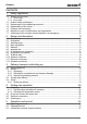
Content Contents 1. Safety regulations 6 1.1 Terms and icons used .......................................................................................................... 6 1.1.1 Terms used .................................................................................................................... 6 1.1.2 Icons used ...................................................................................................................... 6 1.2 Product safety and dangers ............................
Content 5.4 Basic information on operation ........................................................................................ 23 5.4.1 Switching appliance on and off .................................................................................. 23 5.4.2 User interface/controller .............................................................................................. 23 5.4.3 Basic operation ......................................................................................................
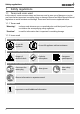
Safety regulations 1. Safety regulations 1.1 Terms and icons used In this manual, certain common terms and icons are used to warn you of dangers or to give you hints that are important in avoiding injury or damage. Observe and follow these hints and regulations to avoid accidents and damage. These terms and icons are explained below. 1.1.1 Terms used “Warning“ is always used whenever you or somebody else could be injured if you do not observe the accompanying safety regulation.
Safety regulations 1.2 Product safety and dangers Constant climate chambers of types HPP 108 and HPP 749 are technically well-developed, manufactured using high-quality materials and are tested for many hours in the factory. They contain the latest technology and comply with recognised technical safety regulations. But there are still dangers involved, even when the appliance is used as intended. These dangers are described below. Warning! After removing covers, live parts may be exposed.
Safety regulations 1.5 Changes and conversions No independent conversions or alterations may be made to the constant climate chamber. No parts may be added or inserted which have not been approved by the manufacturer. Independent conversions or alterations result in the EC declaration of conformity (see page 13) losing its validity, and the constant climate chamber may no longer be operated.
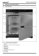
Design and description 2. Design and description 2.1 Construction 1 2 3 11 4 5 6 7 10 8 9 Fig.
Design and description 2.2 Description The constant climate chamber can heat the interior up to 70 ºC and cool it down to 5ºC. For this purpose, low-noise, long-life and energy-saving Peltier cooling and heating technology is used. In heating operation, a part of the required energy is extracted from the surroundings (heat pump principle). Humidity in the interior can be regulated between 10 and 90 % rh (rh = relative humidity).
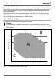
Design and description Range A: In this range, temperature and humidity can be combined as you please, without resulting in any significant condensation. If there are extreme ambient conditions, the working range may be restricted. Range B: If the specified range is exceeded upwards, e.g. 80 % rh at 60°C, the hot steam fed in will immediately condense, due to the dew-point, at the coldest point in the appliance.
Design and description ► 7 different ramp close statements for sophisticated temperature-control tasks ► Acoustic and visual signals if temperature or humidity limits are crossed, and if water tank is empty ► Internal log memory with 1024 kB as a ring memory for all temperature and humidity values, errors and settings with realtime and date, logging for approx.
Design and description 2.7 EC declaration of conformity EC Declaration of Conformity Manufacturer´s name and address: MEMMERT GmbH + Co.
Design and description 2.8 Designation (nameplate) The nameplate provides information about the appliance model, manufacturer and technical data. It is attached to the front of the appliance, on the right beneath the door (see page 9). 9 1 2 3 8 4 7 5 6 Fig. 4 Nameplate 1 Type designation 2 Connection values 3 Applied standard 4 Protection type 5 CE conformity 6 7 8 9 Address of manufacturer Disposal note Nominal temperature range Factory number 2.
Design and description Model HPP 108 HPP 746 Max. load per sliding shelf [kg] 30 30 Max. load per appliance [kg] 60 160 Electrical equipment Operating voltage see nameplate Current consumption see nameplate Protection class 1 (acc. to EN 61010) Protection type IP 20 (EN 60529) Interference-suppressed Class B acc.
Design and description F 75 C Fig. 5 71 12 302 B E 10 38 197 75 D A Dimensions of constant climate chambers HPP 2.10 Ambient conditions ► The constant climate chamber may only be used in enclosed rooms and under the follow- ing environmental conditions: Ambient temperature: 16 ºC to 28ºC Humidity: max. 70 % not condensing Degree of pollution: 2 Altitude of installation: max. 2,000 m above sea level ► The constant climate chamber may not be used in areas where there is a risk of explosions.
Delivery, Transport and Setting Up 3. Delivery, transport and setting up 3.1 Safety regulations Warning! You may get your hands or feet squashed when transporting and installing the constant climate chamber. You should wear protective gloves and work shoes. Warning! Because of the weight of the constant climate chamber, you could cause yourself an injury if you try to lift it. At least two people are needed to carry the constant climate chamber HPP 108, and four for the constant climate chamber HPP 749.
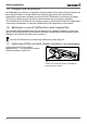
Delivery, Transport and Setting Up The distance between the wall and the rear of the chamber must be at least 15 cm. The clearance from the ceiling must not be less than 20 cm and the side clearance from the wall must not be less than 8 cm (Fig. 6). Sufficient air circulation in the vicinity of the chamber must be guaranteed at all times. FP FP Fig.
Delivery, Transport and Setting Up 3.4.1 Setting up options Read the assembly instructions for the respective accessory part. Floor/table The chambers may be placed on the floor. Constant climate chambers HPP 108 may be placed on a table (work surface), if the table is flat and horizontal and able to bear the weight of the constant climate chamber. Base The chamber can be placed on a base (available as an accessory) (Fig. 7).
Putting into Operation 4. Putting into operation 4.1 Checking 4.1.1 Check the door and adjust if necessary The door may have been twisted during transport. You should therefore check whether the door closes properly and the seals are in the correct position. Adjust door if necessary (description on page 57). 4.1.2 Checking the temperature sensor Due to strong vibrations during transport, the temperature sensors could have moved out of position in their holders in the ceiling of the working chamber.
Putting into Operation 4.3 Electrical connections Caution: Observe the country-specific regulations when making connections (e.g. in Germany DIN VDE 0100 with residual current device (RCD)). Remember the connected loads and power values (see nameplate and also chapter "Technical data" on page 14). The constant climate chamber is intended for operation on an electrical power system with a system impedance Z max at the point of transfer (service line) of a maximum of 0.292 ohm.
Operation and control 5. Operation and control 5.1 Operating personnel The constant climate chamber may only be operated by persons who are of legal age, and who have received instructions for the constant climate chamber. Personnel who are to be trained, instructed or who are undergoing general training may only work with the constant climate chamber under the continuous supervision of an experienced person. 5.2 Opening the door ► To open the door, turn the handle to the right (Fig. 12).
Operation and control 5.4 Basic information on operation 5.4.1 Switching appliance on and off The constant climate chamber is switched on and off by pressing the main switch / push-turn control on the front of the appliance: ► Switching on: press the main switch so that it comes out of the appliance (Fig. 14). ► Switching off: press the main switch so that it retracts back into the appliance (Fig. 15). Fig. 14 Switching on the constant climate chamber Fig.
Operation and control 5.4.3 Basic operation set All settings are selected by turning the push/turn control to the left or right ... ...and adjusted by turning it with the SET key held down. set 5.4.4 Setting parameters Normally, all setting actions on the operating panel described on the following pages are made in the same way: 1. Select the desired parameter with the push/turn control (menu item, e.g. set temperature); then all other parameters go dark and the selected one flashes. 2.
Operation and control 5.6 Operating mode settings 1. Switch on the appliance by pressing the main switch (main switch comes out of appliance, see page 23). set 2. Keep the SET key depressed for approx. three seconds and the selected mode starts flashing. set set 3. Select the desired operating mode/function (normal mode, week time switch, programming mode, printer or basic appliance settings) by turning control with SET key held down. 4. Release the SET key, and the selected operating mode is saved. 5.
Operation and control 5.6.2 Settings example normal mode At a humidity of 70 % rh and 60 % light intensity (optional), the climate chamber should heat up to 37 °C (Fig. 18). 70 °C 60 °C 40 °C 20 °C 100 % 100 % 80 % 80 % 60 % 60 % 40 % 40 % 20 % 20 % t Fig. 18 t t Example for normal mode 1. Setting the normal operating mode: Keep the SET key depressed for approx. 3 seconds and the current operating mode then begins to flash.
Operation and control 5. Setting the humidity setpoint: Turn the push-turn control to the right until the humidity display flashes. Hold down the SET key and set the desired humidity setpoint of 70.0 % rh with the push-turn control. After releasing the SET key the humidity setpoint briefly flashes. Then the current humidity value appears on the display and the controller begins to move to the set value. The humidification process is indicated by the %rh symbol.
Operation and control By turning further to the right, parameters (temperature setpoint etc.) can be selected as in the normal operating mode. If no settings (temperature setpoint etc.) are made for the ON phase, the values from the normal operating mode are used by the controller. For reasons of safety, you should always check that only one switch on time is programmed in the desired time blocks and days.
Operation and control 2. Switch on Mo-Fr at 07.30 Turning the push/turn control to the left and select “MoFr on“ (group working days). Hold down the SET key and set the desired switch-on time with the push/turn switch to 7:30. 3. Switch off Mo–Fr at 18.00 Select “Mo–Fr off“ (group working days) with the push/ turn control. Hold down the SET key and set the desired switch-off time with the push/turn switch to 18:00. 4. Switch on Saturday at 10:00 With the push/turn control, select the “Sat on” icon.
Operation and control You can now select and modify the following parameters in turn (see also the adjustment example on page 34): Mo Tu We Th Fr Sa on 4 t4 t2 h off t3 Su t1 STERI loop IN 1 DEFRO °C 3 2 1 OUT %rh °C mb MAX MIN AUTO SETUP PRINT IN 2 4. Delayed programme start: Switch-on day Adjustment range: Monday to Sunday, workdays Mo-Fr, weekends Sa-Sun, every day Mon-Sun or no days.
Operation and control Tu Mo We Th Fr Sa on 4 t4 t2 h off t3 Su t1 STERI loop IN 1 DEFRO °C 3 2 1 OUT %rh °C mb MAX MIN AUTO SETUP PRINT IN 2 8. Light intensity during the first ramp segment (optional): Adjustment range: 0 % to 100 % in steps of 10%. In the example shown: Light intensity 60 % (six bars are lit up). The interior lighting can only be activated at a working temperature of up to 40 ºC.
Operation and control After releasing the SET key ... ► ... a new programme can be created as described above, or an existing one be edited EDIT ► ... the programme can be stopped STOP ► ... the programme can be started START 5.6.6 Close statements for ramp segments Each ramp must be completed with a close statement connecting the ramp to the next one. These commands thus control the programme sequence: NEXT Connect the next programme segment.
Operation and control Close command ramp segment No. 5 end Se gm en Segment4 nt5 me Delayed programme start Segment2 Close command ramp segment No. 4 next g Se t1 °C Close command ramp segment No. 2 next Se gm en t3 Close command ramp segment No. 1 spwt (t) Close command ramp segment No. 3 spwt (tH) t=time Fig.
Operation and control 5.6.7 Settings example programming mode On Monday at 8:00, the constant climate chamber should heat up to 37 °C, with 50 % light intensity (optional), as quickly as possible and reach a relative humidity of 70 % rh. Once the temperature and humidity have been reached, the constant climate chamber should retain the setpoint values for 45 minutes at 80 % light intensity and then cool down within one hour, at a light intensity of 30 %, to a humidity of 50 % rh and 15 °C (Fig. 21).
Operation and control 1. Setting the programme operating mode: Hold the SET key down for approx. three seconds; the current operating mode then begins to flash. Select the programme operating mode with the push/turn control while holding down the Set key. After releasing the SET key, the controller is in the programme mode. PRINT SETUP 2. Edit programme: Select EDIT with the push/turn control while holding down the SET key. After releasing the SET key, the controller is in the programme write mode. 3.
Operation and control 9. Set the close statement of the first ramp segment: Turn the push/turn control to the right until a segment close statement, e.g. end, appears. Hold down the SET key and set the close statement SPWT [TH] with the push/turn control. 10. Set the duration of the second ramp segment: Turn the push/turn control to the right until the time display flashes. Hold down the SET key and adjust the time to 0:45 with the push/turn control. 11.
Operation and control 17. Setting the light intensity of the third ramp segment (optional): Turn the push-turn control to the right until the lighting display flashes. Hold down the SET key and set the desired light intensity of 30 % with the push-turn control (three bars are lit up). 18. Set the relative humidity of the third ramp segment: Turn the push/turn control to the right until the humidity display flashes. DHold down the SET key and set the desired humidity setpoint to 50.
Operation and control 5.6.8 Operation with computer/laptop (optional) The constant climate chamber can optionally be used, controlled and programmed with a computer/laptop. It has corresponding communication interfaces on the rear side for this purpose (see page 50). The control of the appliance with the “Celsius“ software is described in its own separate manual. 5.7 Ending operation 1. Switch off appliance.
Malfunctions, warning and error messages 6. Malfunctions, warning and error messages Warning! After removing covers, live parts may be exposed. You may receive an electric shock if you touch these parts. Malfunctions requiring intervention inside the appliance may only be rectified by electricians. You must read the separate service manual for this.
Malfunctions, warning and error messages For malfunctions that are not listed here or for error messages on the display (e.g. E-3), please read the service manual for the appliance or contact the MEMMERT customer service if the error correction suggested here is not successful. 6.
Advanced functions 7. Advanced functions 7.1 Printer The constant climate chamber is equipped with a parallel printer port as standard, just as used in computers. A standard PCL3-compatible inkjet printer which has a parallel port interface (e.g. HP DeskJet 5550 or HP DeskJet 9xx) can be connected to the printer port on the rear of the appliance (see page 10). Make sure that a shielded interface cable is used. The shielding must be connected to the plug casing.
Advanced functions Date The controller contains a calendar which automatically accounts for the different lengths of months, and for leap years. Weekday Year Adjustment range: from 2000 to 2100 Acoustic signal at programme end ENDSOUND Setting: OFF or ON Acoustic Signal for alarm, e.g.
Advanced functions The realtime clock, which is set in the SETUP, contains the date and clock time. The realtime clock is used for logging purposes in accordance with GLP. Date and clock time are specified on the log printout. On graphical printouts, the time axis is labeled with the realtime. The clock is battery-buffered and is independent of the mains connection. The integrated Lithium battery of the type CR 2032 has a lifetime of approx. 10 years. 7.
Advanced functions 7.3.1 Electronic temperature monitoring (TWW) Overtemperature protection Adjustment range: -5 ... +75 °C Setting: Select the MAX icon with the push-turn control. Hold down the SET key and adjust the temperature limits with the push/turn control. °C MAX MIN AUTO Undertemperature protection Adjustment range: -5 ... +75 °C °C Setting: MAX Select the MIN icon with the push/turn control. Hold down the MIN SET key and adjust the temperature limits with the push/turn control.
Advanced functions 7.3.2 Automatic temperature monitor (ASF) ASF is a monitoring device that automatically follows the set temperature setpoint within an adjustable tolerance band (Fig. 25). The ASF is activated – if switched on – automatically if the actual temperature value reaches 50% of the set tolerance band of the setpoint (in the example 50°C ± 1°C) is reached for the first time (section A). The activation of the ASF is shown by the brightly lit AUTO icon.
Advanced functions Switching on the automatic temperature monitor: Select the AUTO icon with the push/turn control. Hold down the SET key and set to on with the push-turn control. °C MAX MIN AUTO Switching off the automatic temperature monitor: Select the AUTO icon with the push/turn control. Hold down the SET key and set to off with the push/turn control. °C MAX MIN AUTO The tolerance band for the ASF can be adjusted in the SETUP (see page 42). 7.3.
Advanced functions 7.4 Heat output distribution (BALANCE) For constant climate chambers HPP 749, application-specific correction of the heat output distribution (BALANCE) is possible between the upper and lower heating groups in the SETUP (setting: see page 42). The adjustment range is from –50 % to +50 %. Setting 0 % restores the heating output distribution factory settings. upper heat output upper heat output lower heat output lower heat output -20% +30% Fig.
Advanced functions 7.5 Calibration 7.5.1 Temperature calibration The constante climate chamber can be calibrated customer-specifically using three calibration temperatures of your choice: ► CAL.1 temperature calibration at low temperature ► CAL.2 temperature calibration at medium temperature ► CAL.3 temperature calibration at high temperature For each selected balance point (Fig. 27) a positive or negative compensation correction value can be set between –4.9 ºC and +4.9 ºC.
Advanced functions Example: Temperature deviation at 30 °C should be corrected. 1. Set compensation temperature CAL.2 in the SETUP to 30.0°C and set accompanying compensation correction value to 0.0°C: h °C °C 2. With a calibrated reference instrument and at a set setpoint temperature of 30 °C in normal operation, an actual temperature of 29.6 °C is measured. 3. Set the compensation correction value for CAL.2 in the SETUP to - 0.4°C: h °C °C 4.
Advanced functions Setting: 1. Set the desired humidity balance point in the SETUP (see page 42) and set the accompanying compensation correction value to 0.0 %rh. 2. With a reference instrument, measure the deviation in the stationary state in the selected humidity balance point. 3. Set the compensation correction value in the SETUP. If the measured reference humidity is too low, the compensation correction value must be set with a negative sign. 4.
Advanced functions 7.6.2 Communication interfaces RS232/RS485 (optional) The chamber can be optionally equipped with a RS232 serial communication interface in accordance with DIN 12900-1 or a RS485 interface, instead of a USB interface (Fig. 29 and Fig. 30). ► With the RS232 interface, it is possible to control and log the chamber remotely from the computer.
Advanced functions 7.6.3 Connecting test chambers to a network with Ethernet interface The constant climate chamber can optionally be equipped with an Ethernet instead of a USB interface. LAN 3: 192.168.1.241 LAN 2: 192.168.1.215 LAN 1: 192.168.1.233 192.168.1.216 Fig. 31 Connecting one or more test chambers to a network using an Ethernet interface (schematic diagram) For identification purposes, each appliance connected must have its own unique IP address.
Advanced functions If the power supply is interrupted, the time of the power cut and the return of voltage are stored in the controller. Reading in the log memory to the computer via USB interface Using the “Celsius“ progamme, the log memory of the controller can be read out to a computer and from there be displayed graphically, printed out and stored. The log memory of the controller is not modified or deleted by the reading out.
Advanced functions 3. Programme the chamber on the computer. The chosen settings are written and stored on the card. Via the “Celsius“ software, the MEMoryCard XL can be provided with write protection. The programme on the card can then no longer be altered on the controller. Programme alterations via the controller are only possible if the write protection has been disabled from the computer with the “Celsius“ software.
Advanced functions 7.6.6 User ID card (optionally available as an accessory) The device number of the appliance and an unique user number are stored in encrypted form on the User-ID card (Fig. 34). The User-ID card therefore works only in the appliance with the corresponding serial number. Every login process with the User-ID card is Name: logged in the internal Flash memory of the _____________________ access ID: authority controller.
Maintenance and Servicing 8. Maintenance and servicing Warning! Disconnect the mains plug before any cleaning or maintenance work. 8.1 Cleaning Regular cleaning of the easy to clean chamber interior prevents build up of material remains, which over time could impair the appearance and functionality of the stainless steel chamber. The metal surfaces of the chamber can be cleaned with normal stainless steel cleaning agents.
Maintenance and Servicing 8.3 Adjusting door A well-closing door is indispensable for climate chambers. On Memmert appliances, the tight closing of the door is optimally guaranteed by a chamber seal and a door seal. In permanent operation, it is possible that the flexible seal material will begin to sag. To ensure that the door closes exactly, however, an adjustment may be necessary: 1. Undo mounting bolts (Fig. 36, 2) at the top and bottom of door. 2.
Storage and disposal 9. Storage and disposal 9.1 Storage The constant climate chamber may only be stored under the following conditions. ► dry and in an enclosed, dust-free room ► frost-free ► disconnected from the power supply Before storage, remove the water tube and empty the water tank (see page 21). 9.2 Disposal This product is subject to the directive 2002/96/EC on Waste Electrical and Electronic Equipment (WEEE) of the European Parliament and of the EU Council of Ministers.
Index Index A I S Acoustic signal 42 Adjusting door 57 Ambient conditions 16 Intended use 12 Interior light 3, 12, 26 Irregularities 8, 17 B L BALANCE 47 Base 19 Basic operation 24 Laptop 38 LED 3, 12 Light 3, 12, 23, 25, 26, 34, 35, 36, 37, 39 Light intensity 31 Load 15 Loading 22 Safety regulations 6 Service 57 Servicing 56 Setting parameters 24 Settings example normal mode 26 Settings example programming mode 34 Settings example week time switch 28 Setting up 17 Setting up options 19 Setup 17 S
Memmert GmbH + Co KG | Postfach 1720 | D-91107 Schwabach | Tel. +49 (0) 9122-925-0 | Fax +49 (0) 9122-145-85 | E-Mail: service@memmert.com | www.memmert.com 27.01.