
User manual


Basic OperationRev 1.0
Mellanox Technologies
16
2 Basic Operation
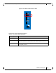
2.1 Switch Platform Hardware Overview
switchFigure 5 shows the connector side panel views of the internally managed switches. The
figure shows port configurations for the switch systems.Managed systems have:
• 1 – Ethernet RJ-45 connector for management
• 1 – RJ-45 connector for connecting to a host PC
• 1 – USB connector.
Externally managed switches only have a single I2C RJ-45 connector. All switches have various
status LEDs for on site status information.
Figure 5: Switch System Connector Side Panels
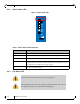
2.2 Status LEDs
The System Status LEDs are located to the left of the connectors on the connector side panel.
2.2.1 System Status LEDs
Figure 6: Externally Managed System Status LEDS
RST
PS1
UID
Mellanox
SX6012
PS2
1
2
3
4
5
6
7
8
9
10
11
12
RST
PS1
UID
Mellanox
SX6005
PS2
I2C
1
2
3
4
5
6
7
8
9
10
11
12