
User manual

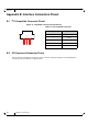

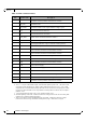
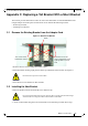


Table Of Contents
- ConnectX®-2 EN Dual Port SFP+ Ethernet Adapter Card User Manual
- Table of Contents
- List of Figures
- List of Tables
- Revision History
- About this Manual
- 1 Overview
- 2 Adapter Card Interfaces
- 3 Driver Software and Firmware
- 4 Ethernet Adapter Card Installation
- Appendix A: Specifications
- Appendix B: Interface Connectors Pinout
- Appendix C: Replacing a Tall Bracket With a Short Bracket
- Appendix D: Avertissements de sécurité d’installation (Warnings in French)
- Appendix E: Sicherheitshinweise (Warnings in German)
- Appendix F: Advertencias de seguridad para la instalación (Warnings in Spanish)
Rev 1.6
Mellanox Technologies
42
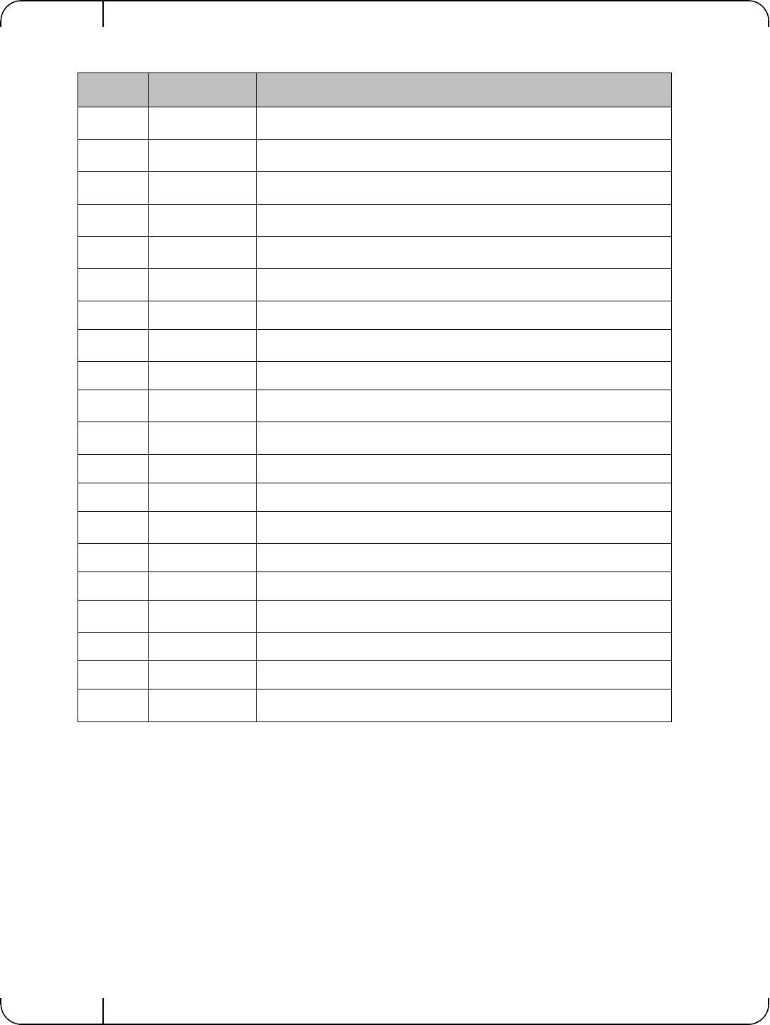
Table 14 - SFP+ Connector Pinout
Pin Symbol Name Description
1 VeeT
Transmitter Ground (Common with Receiver Ground)
a
a. Circuit ground is internally isolated from chassis ground.
2 TX_Fault
Transmitter Fault.
b
b. T
FAULT
is an open collector/drain output, which should be pulled up with a 4.7k – 10k Ohms resistor
on the host board if intended for use. Pull up voltage should be between 2.0V to Vcc + 0.3V. A high
output indicates a transmitter fault caused by either the TX bias current or the TX output power exceed-
ing the preset alarm thresholds. A low output indicates normal operation. In the low state, the output is
pulled to <0.8V.
3 TX_Disable
Transmitter Disable. Laser output disabled on high or open.
c
c. Laser output disabled on TDIS >2.0V or open, enabled on TDIS <0.8V
4 SDA
2-wire Serial Interface Data Line
d
d. Should be pulled up with 4.7kΩ – 10kΩ on host board to a voltage between 2.0V and 3.6V. MOD_ABS
pulls line low to indicate module is plugged in.
5 SCL
2-wire Serial Interface Clock Line
d
6 MOD_ABS
Module Absent. Grounded within the module
d
7 RS0 No connection required
8 RX_LOS
Loss of Signal indication. Logic 0 indicates normal operation.
e
e. LOS is open collector output. Should be pulled up with 4.7kΩ – 10kΩ on host board to a voltage
between 2.0V and 3.6V. Logic 0 indicates normal operation; logic 1 indicates loss of signal.
9 RS1 No connection required
10 VeeR
Receiver Ground (Common with Transmitter Ground)
a
11 VeeR
Receiver Ground (Common with Transmitter Ground)
a
12 RD- Receiver Inverted DATA out. AC Coupled
13 RD+ Receiver Non-inverted DATA out. AC Coupled
14 VeeR
Receiver Ground (Common with Transmitter Ground)
a
15 VccR Receiver Power Supply
16 VccT Transmitter Power Supply
17 VeeT
Transmitter Ground (Common with Receiver Ground)
a
18 TD+ Transmitter Non-Inverted DATA in. AC Coupled.
19 TD- Transmitter Inverted DATA in. AC Coupled.
20 VeeT
Transmitter Ground (Common with Receiver Ground)
a