ConnectX®-2 EN Dual Port SFP+ Ethernet Adapter Card User Manual P/N: MNPH29C-XSR, MNPH29C-XTR, MNPH29D-XSR, MNPH29D-XTR Rev 1.6 www.mellanox.
Rev 1.6 NOTE: THIS HARDWARE, SOFTWARE OR TEST SUITE PRODUCT (“PRODUCT(S)”) AND ITS RELATED DOCUMENTATION ARE PROVIDED BY MELLANOX TECHNOLOGIES “AS-IS” WITH ALL FAULTS OF ANY KIND AND SOLELY FOR THE PURPOSE OF AIDING THE CUSTOMER IN TESTING APPLICATIONS THAT USE THE PRODUCTS IN DESIGNATED SOLUTIONS. THE CUSTOMER'S MANUFACTURING TEST ENVIRONMENT HAS NOT MET THE STANDARDS SET BY MELLANOX TECHNOLOGIES TO FULLY QUALIFY THE PRODUCTO(S) AND/OR THE SYSTEM USING IT.
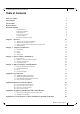
ConnectX-2 Ethernet Card User Manual Rev 1.6 Table of Contents Table of Contents 3 List of Figures 5 List of Tables 6 Revision History 7 About this Manual 8 Intended Audience Related Documentation Online Resources Document Conventions Technical Support Firmware and Software Updates 8 8 8 8 8 9 Chapter 1 Overview 1.1 1.2 1.3 1.
Rev 1.
ConnectX-2 Ethernet Card User Manual Rev 1.
Rev 1.
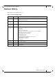
ConnectX-2 Ethernet Card User Manual Rev 1.6 Revision History This document was printed on 2/15/11. Table 1 - Revision History Table Date Rev Comments/Changes Jan. 2011 1.6 Changed Air flow requirement Added to the Set up section Dec. 19th, 2010 1.5 Minor formatting changes Nov. 22nd, 2010 1.4 Added Generation D card Mini Form Factor Oct. 28th, 2010 1.
Rev 1.6 About this Manual This User Manual describes Mellanox Technologies ConnectX®-2 Dual Port 10Gigabit Ethernet PCI Express x8 adapter cards. It provides details as to the interfaces of the board, specifications, required software and firmware for operating the board, and relevant documentation. Intended Audience This manual is intended for the installer and user of these cards. The manual assumes basic familiarity with Ethernet networks and architecture specifications.
ConnectX-2 Ethernet Card User Manual Rev 1.6 • Tel: +1.408.916.0055 Customers who purchased Mellanox M-1 Global Support Services, please see your contract for details regarding Technical Support. Customers who purchased Mellanox products through a Mellanox approved reseller should first seek assistance through their reseller. Firmware and Software Updates The Mellanox support downloader contains software, firmware and knowledge database information for Mellanox products.
Rev 1.6 1 Overview Overview This document is a User Manual for Mellanox Technologies cards based on the ConnectX®-2 ENintegrated circuit device. The cards described in this manual have the following main features: • IEEE Std 802.3 compliant • 10 Gb/s Ethernet • Dual SFP+ ports for connection Ethernet traffic • PCI Express 2.0 (1.
ConnectX-2 Ethernet Card User Manual 1.1 Rev 1.6 Adapter Cards Covered in this Manual Table 3 lists the Ethernet adapter cards described in this manual. Table 3 - Network Interface Cards Ordering Part Number (OPN) MNPH29D-XTR PCI Express SERDES Speed Data Transmission Rate/ # of ports PCIe Gen2 5.
Rev 1.
ConnectX-2 Ethernet Card User Manual 1.2 Rev 1.6 Mellanox Part Numbering Legend Table 4 describes the Mellanox Technologies adapter cards part numbering legend.
Rev 1.6 1.3 Overview Finding the MAC and Serial Number on the Adapter Cards All Mellanox adapter cards have a label on the printed side of the adapter card that has the card serial number, and the card MAC. Figure 2: Card Product Label S/N:MT0744X00012 REV: X1 P/N:MNPH29C-XTR MAC: 0002C9020040DDB0 Made in IL Port 1 uses the GUID or MAC ID described on the label, for port 2 GUID or MAC add 1 to port 1's description. 1.
ConnectX-2 Ethernet Card User Manual Rev 1.6 3. During Lightning - Electrical Hazard During periods of lightning activity, do not work on the equipment or connect or disconnect cables. 4. Copper Cable Connecting/Disconnecting Some copper cables are heavy and not flexible, as such they should be carefully attached to or detached from the connectors. Refer to the cable manufacturer for special warnings and instructions. 5.
Rev 1.6 Adapter Card Interfaces 2 Adapter Card Interfaces 2.1 I/O Interfaces Each card includes the following interfaces: • SFP+ ports • I/O panel LEDs • I2C compatible connector (for debug) For dual port cards, port 1 connects to connector 1 of the device, while port 2 connects to connector 2 of the device. ConnectX-2 Ethernet Adapter Cards are compliant with the IEEE Std 802.3 Specification. Figure 3: Port Numbering Port 1 Port 2 2.1.
ConnectX-2 Ethernet Card User Manual Rev 1.6 2.1.3 LED Assignment The board has I/O LEDs located on the I/O panel. The green LED, when lit, indicates that the driver is running and a valid physical connection between nodes exists. If the green LED is blinking, it indicates a problem with the physical link. The yellow LED when lit, indicates a valid data activity link, this is the logical link. The yellow LED lights up when the network is discovered over the physical link.
Rev 1.6 Adapter Card Interfaces The short bracket has the same port and LED footprint as the tall bracket. 2.1.4 I2C Compatible Interface A three-pin header on the card is provided as the I2C compatible interface. See Appendix A,“Specifications,” on page 34 for the location on the board. Figure 6: I2C Connector 2.2 Power All adapter cards receive 12V and 3.3V power from the PCI Express Edge connector. All other required power voltages are generated by on-board switch mode regulators.
ConnectX-2 Ethernet Card User Manual Rev 1.6 Table 6 - Jumper Configuration Description Flash present/ not present Card Default Configuration Option connection open – Flash present connection shorted – Flash not present Comments connection open – Flash present Header 1x2 Figure 7: Flash Jumper 2.3.3 EEPROM Each board incorporates an EEPROM that is accessible through the I2C. The EEPROM is used for storing the Vital Product Data (VPD). The EEPROM capacity is 4Kb. 2.
Rev 1.
ConnectX-2 Ethernet Card User Manual Rev 1.
Rev 1.6 Driver Software and Firmware 3 Driver Software and Firmware 3.1 Driver Software 3.1.1 Linux For Linux, download and install the latest MLNX_EN driver software package available via the Mellanox Web site at: http://www.mellanox.com => Downloads => Ethernet SW/Drivers. Follow the installation instructions included in the download package. 3.1.2 Windows For Windows, download the MLNX EN – Ethernet driver. Download this package from the Mellanox Web site at: http://www.mellanox.
ConnectX-2 Ethernet Card User Manual 3.3 Rev 1.6 Updating Card Firmware Each card is shipped with the latest version of qualified firmware at the time of manufacturing. Firmware is updated occasionally, and the most recent firmware can be obtained from: http://www.mellanox.com =>Support > Download Center. Check that the firmware on your card is the latest found on the Mellanox site, if not update to the latest version found on the Mellanox website.
Rev 1.6 Driver Software and Firmware Figure 8: Support Download Assistant 3.4 ConnectX EN PXE The Mellanox ConnectX EN PXE solution enables the booting of servers from an IP based LAN environment. To enable or disable PXE use the following procedure: The user must use the MFT tools: To disable one must delete the PXE ROM image from the flash. To enable one must place the PXE ROM image to the flash. This software is based on the open source Etherboot/gPXE project (see www.etherboot.org).
ConnectX-2 Ethernet Card User Manual Rev 1.6 4 Ethernet Adapter Card Installation 4.1 Hardware and Software Requirements Before installing the adapter card, please make sure that the system meets the hardware and software requirements listed in Table 9. Refer to Chapter 3,“Driver Software and Firmware” on page 22 for download and installation instructions.
Rev 1.6 Ethernet Adapter Card Installation Any PCI slot with the proper configuration is acceptable for connection. If the card is installed in a PCI slot with less lanes than the card requires then the adapter card will not provide the optimum data transfer. 4.3 Set Up This section is valid for InfiniBand, Ethernet and VPI cards. Disregard sections that are not relevant to your card. The basic steps to embed Mellanox cards in your computer are: 1. Identify the card in your system. 2.
ConnectX-2 Ethernet Card User Manual Rev 1.6 Figure 9: Hardware Devices 3. Select a PCI Device / InfiniBand Controller entry. 4. Right-click. 5. Select “Properties to display the PCI Device Properties” window. 6. Click the Details tab and select Device Instance Id (Windows 2003) or Hardware Ids (Windows 2008/R2) from the Property pull-down menu.
Rev 1.6 Ethernet Adapter Card Installation Figure 10: PCI Device 7. In the Value display box, check the fields VEN and DEV (fields are separated by ‘&’). In the display example above, notice the sub-string “PCI\VEN_15B3&DEV_6368”: VEN is equal to 0x15B3 – this is the Vendor ID of Mellanox Technologies; and DEV is equal to 0x6368 – this is a valid Mellanox Technologies PCI Device ID. The list of Mellanox Technologies PCI Device IDs can be found in the PCI ID repository at http://pci-ids.ucw.
ConnectX-2 Ethernet Card User Manual Rev 1.6 4.3.1.2 Linux Get the device location on the PCI bus by running lspci and locating lines with the string “Mellanox Technologies”: > lspci | grep Mellanox 2:00.0 InfiniBand: Mellanox Technologies MT26428 [ConnectX VPI PCIe 2.0 5GT/s - IB QDR / 10GigE] (rev b0) Make sure that either the MLNX_OFED driver or the MLNX_EN driver is loaded and configured. Check the link status First check the network interface name by running the “ifconfig –a” command.
Rev 1.6 Ethernet Adapter Card Installation Rate: 10 Base lid: 6 LMC: 0 SM lid: 3 Capability mask: 0x0251086a Port GUID: 0x0002c903000c8711 Link layer: IB Check the OFED version To get the version of the running Mellanox OFED/BXOFED, run the following command: Host# ofed_info | head -1 BXOFED-1.5.1-1.3.7-rc19: Troubleshooting MLNX_OFED Installation For troubleshooting driver installation, please check Mellanox OFED driver user manual: http://www.mellanox.com => Support > Adapter IB/VPI SW.
ConnectX-2 Ethernet Card User Manual Rev 1.6 The “Usage: openibd {start|stop|restart|status}” command to modify this file and thereby control the drivers. Ethernet Driver Usage and Configuration To assign an IP address to the interface run: #> ifconfig eth where 'n' is the OS assigned interface number. • To check driver and device information run: #> ethtool -i eth Example: #> ethtool -i eth2 driver: mlx4_en (MT_04A0140005) version: 1.5.1 (March 2010) firmware-version: 2.7.
Rev 1.6 Ethernet Adapter Card Installation The adapter cards are shipped without optical modules. Mellanox 10GBASE-SR (MFM1T02ASR) and 10GBASE-LR (MFM1T02A-LR) optical modules are recommended. The figure below shows the Mellanox SFP+ module. Inserting the Optical Transceiver Module To insert the module into the cage: 1. Open the module’s locking mechanism – see Figure 11 and Figure 12. 2. Make sure that the male connectors on the module will align with the female connectors inside of the cage.
ConnectX-2 Ethernet Card User Manual Rev 1.6 Always install and remove cables by pushing or pulling the cable and connector in a straight line with the card. Care should be taken not to impede the air exhaust flow through the ventilation holes. Cable lengths should be used which allow for routing horizontally around to the side of the chassis before bending upward or downward in the rack. To remove a cable, disengage the locks and slowly pull the connector away from the port receptacle.
Rev 1.6 Appendix A: Specifications A.1 MNPH29D-X[ST]R Specifications Table 10 - Specifications for MNPH29D-X[ST]R Physical Size: Air Flow: 10Gb/s Connector: 2.71in x5.60in (68.90mm x 142.25mm) Power and Environmental Voltage: Typ. Power: Passive Cables 6.43W Active Cables 7.83W Maximum Power: Passive Cables 7.08W Active Cables 8.48W a 200LFM SFP+ Temperature: Protocol Support Ethernet: PCI Express IEEE Std 802.3ae 10 Gigabit Ethernet IEEE Std 802.3ad Link Aggregation and Failover IEEE Std 802.
ConnectX-2 Ethernet Card User Manual A.2 Rev 1.6 MNPH29C-X[ST]R Specifications Table 11 - Specifications for MNPH29C-X[ST]R Physical Size: Air Flow: 10Gb/s Connector: 2.71in x6.60in (68.90mm x 167.65mm) Power and Environmental Voltage: Typ. Power: Passive Cables 6.43W Active Cables 7.83W Maximum Power: Passive Cables 7.08W Active Cables 8.48W 200LFMa SFP+ Temperature: Protocol Support Ethernet: PCI Express 12V, 3.3V 0°C to 55°C Regulatory IEEE Std 802.3ae 10 Gigabit Ethernet IEEE Std 802.
Rev 1.6 All dimensions are in millimeters. All the mechanical tolerances are +/-0.1mm Figure 13: Schematic of the ConnectX-2 Small Form Factor MNPH29D Adapter Card 142.25 J7 Q1 Q2 U1 J8 64.40 U14 U3 56.15 J4 L8 J1 J3 U4 12.75 15.00 45.96 3.65 45.01 36 Mellanox Technologies 1.
ConnectX-2 Ethernet Card User Manual Rev 1.6 Figure 14: Schematic of the ConnectX-2 Card MNPH29C Adapter Card J2 – I2C Connector J3 – Flash Jumper 15.00 U25 3.65 L17 68.90 U19 1.90 33.35 43.17 57.15 A.4 U14 U18 U1 J5 J4 J6 U4 L7 J7 64.40 56.97 U2 J1 J2 U3 167.65 96.30 EMC Certification Statements Table 12 lists the approved certification status per in different regions of the world.
Rev 1.6 A.4.1 FCC Statements (USA) Class A Statements: § 15.19(a)(4) This device complies with Part 15 of the FCC Rules. Operation is subject to the following two conditions: 1. This device may not cause harmful interference, and 2. This device must accept any interference received, including interference that may cause undesired operation. § 15.
ConnectX-2 Ethernet Card User Manual A.4.4 Rev 1.6 VCCI Statements (Japan) Class A Statement: (Translation - "This is a Class A product based on the standard of the Voluntary Control Council for Interference by Information Technology Equipment (VCCI). If this equipment is used in a domestic environment, radio interference may occur, in which case the user may be required to take corrective actions.") A.4.
Rev 1.6 Appendix B: Interface Connectors Pinout B.1 I2C-Compatible Connector Pinout Figure 15: Compatible Connector Plug and Pinout Table 13 - I2C-Compatible Connector B.2 4 3 2 1 5 5 1 2 3 4 Connector Pin Number Signal Name 1 SPSDA 2 SPSCL 3 GND 4 NC 5 NC PCI Express x8Connector Pinout These cards use a standard PCI Express x8 edge connector and the PCI Express x8 standard pinout according to the PCI Express 2.0 specification.
ConnectX-2 Ethernet Card User Manual Rev 1.6 B.3 PCI Express Connector Pinout B.4 SFP+ Connector Pinout Figure 16: Rear View of Module With Pin Placement Top 13.70 8.
Rev 1.6 Table 14 - SFP+ Connector Pinout Pin Symbol Name Description 1 VeeT Transmitter Ground (Common with Receiver Ground) a 2 TX_Fault Transmitter Fault.b 3 TX_Disable Transmitter Disable. Laser output disabled on high or open. c 4 SDA 2-wire Serial Interface Data Line d 5 SCL 2-wire Serial Interface Clock Line d 6 MOD_ABS Module Absent. Grounded within the module d 7 RS0 No connection required 8 RX_LOS Loss of Signal indication. Logic 0 indicates normal operation.
ConnectX-2 Ethernet Card User Manual Rev 1.6 Appendix C: Replacing a Tall Bracket With a Short Bracket This section provides instructions on how to remove the tall bracket of a standard Mellanox Technologies adapter card and replace it with a short one. It includes the following sections: • Removing a bracket • Installing a new bracket C.
Rev 1.6 Figure 18: Putting on the Bracket 6. Make sure that the LEDs are aligned onto the bracket holes. 7. Use a torque driver to apply up to 2 lbs-in torque on the screws.
ConnectX-2 Ethernet Card User Manual Rev 1.6 Appendix D: Avertissements de sécurité d’installation (Warnings in French) 1. Instructions d’installation Lisez toutes les instructions d’installation avant de brancher le matériel à la source d’alimentation électrique. 2. Température excessive Ce matériel ne doit pas fonctionner dans une zone avec une température ambiante dépassant le maximum recommandé de 55°C (131°F). Un flux d’air de 200LFM à cette température ambiante maximale est nécessaire.
Rev 1.6 Appendix E: Sicherheitshinweise (Warnings in German) 1. Installationsanleitungen Lesen Sie alle Installationsanleitungen, bevor Sie das Gerät an die Stromversorgung anschließen. 2. Übertemperatur Dieses Gerät sollte nicht in einem Bereich mit einer Umgebungstemperatur über der maximal empfohlenen Temperatur von 55°C (131°F) betrieben werden. Es ist ein Luftstrom von 200 LFM bei maximaler Umgebungstemperatur erforderlich. Außerdem sollten mindestens 8 cm (3 in.
ConnectX-2 Ethernet Card User Manual Rev 1.6 Appendix F: Advertencias de seguridad para la instalación (Warnings in Spanish) 1. Instrucciones de instalación Antes de conectar el equipo a la fuente de alimentación, leer todas las instrucciones de instalación. 2. Sobrecalentamiento No se debe utilizar el equipo en un área con una temperatura ambiente superior a la máxima recomendada: 55°C(131°F).
Rev 1.6 Códigos eléctricos locales y nacionales Este equipo se debe instalar conforme a los códigos eléctricos locales y nacionales.