
Technical data


48
ATTENTION Possible data loss or corruption – Wait for the blue Controller
Service Action Allowed LED on controller A to come on before you turn off the power
to either controller; otherwise, possible data loss or corruption might occur.
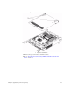
Figure 33 Controller LEDs
1. Controller Service Action Allowed LED (Blue)
2. Controller Service Action Required LED (Amber)
7. Turn off the Power switch on each of the power-fan canisters, and wait until all
LED and seven-segment display activity on the rear of the controller-drive tray
has stopped.
Figure 34 Power Switches on the E5460 Controller-Drive Tray
1. Power Switch for Controller A
2. Power Switch for Controller B
8. Disconnect the following cables from both controller canisters.
— Host interface cables
— Drive interface cables
— Ethernet cables
If fiber-optic cables are present, you can lift the two release levers and partially
remove the controller canister. Opening these release levers makes it easier to
press down on the fiber-optic cable release tab.