SGI InfiniteStorage 4000 Series and 5000 Series System Upgrade Guide (ISSM 10.
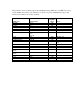
The information in this document supports the SGI InfiniteStorage 4000 series and 5000 series storage systems (ISSM 10.83). Refer to the table below to match your specific SGI InfiniteStorage product with the model numbers used in this document.
Copyright information Copyright © 1994–2012 NetApp, Inc. All rights reserved. Printed in the U.S.A. No part of this document covered by copyright may be reproduced in any form or by any means— graphic, electronic, or mechanical, including photocopying, recording, taping, or storage in an electronic retrieval system—without prior written permission of the copyright owner.
Trademark information NetApp, the NetApp logo, Network Appliance, the Network Appliance logo, Akorri, ApplianceWatch, ASUP, AutoSupport, BalancePoint, BalancePoint Predictor, Bycast, Campaign Express, ComplianceClock, Cryptainer, CryptoShred, Data ONTAP, DataFabric, DataFort, Decru, Decru DataFort, DenseStak, Engenio, Engenio logo, E-Stack, FAServer, FastStak, FilerView, FlexCache, FlexClone, FlexPod, FlexScale, FlexShare, FlexSuite, FlexVol, FPolicy, GetSuccessful, gFiler, Go further, faster, Imagine Virtu
Table of Contents Chapter 1 Preparing to Upgrade Your Storage Management Software . . . . . . . . . . . . . . . . 1 Upgrading the Storage Management Software and the Controller Firmware . . . 1 Storage Management Software Packages. . . . . . . . . . . . . . . . . . . . . . . . . . . . . . . 3 Installation Options . . . . . . . . . . . . . . . . . . . . . . . . . . . . . . . . . . . . . . . . . . . . 5 Checking the Current Version of the Storage Management Software . . . . .
Chapter 5 Upgrade Instructions for the Solaris OS . . . . . . . . . . . . . . . . . . . . . . . . . . . . . . . 111 Supported Components for Solaris. . . . . . . . . . . . . . . . . . . . . . . . . . . . . . . . . . 111 Installing the Storage Management Software on the Solaris OS . . . . . . . . . . . 113 Checking the Installation on the Solaris OS. . . . . . . . . . . . . . . . . . . . . . . . . . . 115 Uninstalling the Storage Management Software on the Solaris OS. . . . . . . . .
Preparing the Storage Array as a Boot Device . . . . . . . . . . . . . . . . . . . . . 146 Preparing the Host. . . . . . . . . . . . . . . . . . . . . . . . . . . . . . . . . . . . . . . . . . . 151 Completing the Installation Process . . . . . . . . . . . . . . . . . . . . . . . . . . . . .
viii Table of Contents
Preparing to Upgrade Your Storage Management Software 1 The following table shows the supported upgrade paths for controller trays and controller-drive trays for storage management software version 10.83 and controller firmware version 7.83. Table 1 Supported Trays and Software Upgrade Paths Tray Name Installed Storage Management Software Version Installed Controller Firmware Version Controller-drive trays E2612, E2624, E2660 10.70 or later 7.70 or later CE4900 10.60 or later 7.
NOTE Install all storage area network (SAN) hardware before you work with the storage management software. 3. Start the existing storage management software with the procedure for your operating system. 4. Check that the storage array has Optimal status. 5. Save and print the storage array profile from the current Array Management Window of the storage management software for each storage array. a. In the Array Management Window, select Monitor >> Report >> Storage Array Profile. b.
13. Check that the storage array has an Optimal status. If one or more managed devices has a Needs Attention status, contact your Technical Support representative. 14. If you determined from the storage array profile that the NVSRAM firmware, the controller firmware, or the ESM firmware is not the current version, download the compatible firmware. NOTE With the I/O Shipping feature, a storage array can use asymmetric logical unit access (ALUA).
Software Package Description and Usage Redundant Dual Active Controller (RDAC)/Multi-Path Proxy (MPP) A multi-path failover driver, proprietary to NetApp, that is installed on Linux hosts. This software package manages the I/O paths into the controllers in the storage array. If a problem exists on the path or a failure occurs on one of the controllers, the driver automatically reroutes the request from the hosts to the other controller in the storage array.
Installation Options Install only the packages that are required for the type of installation you are performing.
Supported Controller Trays and Controller-Drive Trays Maximum Number of Drives and Volumes for Controller-Drive Trays and Controller Trays This section describes the supported controller trays and controller-drive trays. Table 4 Controller Trays and Controller-Drive Trays Term Description Controller tray A unit that contains one or two controllers, a battery (optional), and redundant cooling fans and power supplies. Controller trays do not contain environmental services modules (ESMs).
Table 6 Co-existing Trays and the Maximum Number of Drives and Volumes Tray Name Controller Type Maximum Drives per Storage Array Maximum Volumes per Storage Array1 Controller-drive trays SHV2520 2880 (dual) 142 1024 SHV2600 2882 112 1024 SAT2700 2820-SATA 14 2 512 SAT2800 2822-SATA 112 512 CDE3994 3992 or 3994 112 1024 FC1250 4884 224 2048 FC1275 5884 224 2048 CE6998 6091 224 2048 Controller trays 1 Snapshot (Legacy) repository volumes and Synchronous Mirroring repos
Supported Storage Array Configurations 8 The drive tray is a unit that contains up to 16 drives, redundant cooling fans and power supplies, and one or two ESMs. Drive trays do not contain controllers.
Upgrading Trays in the Storage Array 2 Keep these guidelines in mind before you upgrade trays in your storage array: Always back up your data to an external source before starting an upgrade procedure. Keep in mind that requirements for SFPs and cabling might change when you upgrade a host adapter. Refer to the Hardware Cabling Guide for a complete description of various cabling options.
Upgrading Options for Supported Trays Table 1 Upgrading Options for Supported Trays Tray Name Tray Upgrading Option Upgrade Host Adapters CE7900 Upgrade 4-Gb/s FC to 8-Gb/s FC. Upgrade 1-Gb/s iSCSI to 10-Gb/s iSCSI. Install a second HIC (4-Gb/s FC, 8-Gb/s FC, 1-Gb/s iSCSI, 10-Gb/s iSCSI). E5400 Install a HIC in addition to the base host ports (8-Gb/s FC or 40-Gb/s InfiniBand). E2600 Install a HIC in addition to the base host ports (8-Gb/s FC, 1-Gb/s iSCSI, 10-Gb/s iSCSI, 6-Gb/s SAS).
Upgrading Cache Memory for the CE7900 Controller Tray Each controller canister in the E5400 controller-drive tray has two sockets for cache memory DIMMs and a cache backup memory device. Use this procedure to upgrade existing cache memory DIMMs and, if necessary, add a cache backup memory device. Each controller canister in the E2600 controller-drive tray has one socket for cache memory DIMMs and a cache backup memory device.
1. Gather support data about your updated storage array by using one of these methods: SANtricity ES From the Array Management Window toolbar, select Monitor >> Health >> Collect Support Data. Then name and specify a location on your system where you want to store the support bundle. Command line interface Enter the following command on the command line: save storageArray supportData This command gathers comprehensive support data about the storage array.
6. Use one of the following options to place controller A offline. SANtricity ES From the Hardware pane in the Array Management Window, right-click the picture of the controller, and select Advanced >> Place >> Offline. Command line interface Enter the following command on the command line: smCLI -c “set controller [a] availability=offline”; In this command, is the applicable address.
Figure 1 Removing a Controller 1. Release Handles 2. Locking Mechanisms 3. Controller Canister 11. Remove the cover on both controller canisters. 14 a. Loosen the thumbscrews that secure the cover to the controller canister. b. Lift the cover off of the controller canister as shown in the following figures.
Figure 2 Controller Top Cover, Internal Parts, and Faceplate 1. Cache Backup Memory Device Slot Locations 2. Cache Memory DIMM Slot Locations 12. Go to "Upgrading a Cache Memory DIMM in the CE7900 Controller Canister" on page 15. Upgrading a Cache Memory DIMM in the CE7900 Controller Canister If you are upgrading the cache memory DIMMs in one controller canister, you must increase the capacity of the cache memory DIMMs in the other controller canister in the CE7900 controller tray.
Total Cache Number of Cache Capacity of Each Memory per Memory DIMMs Cache Memory Controller (GB) per Controller DIMM (GB) 1. Cache DIMM Slots Populated 4 4 1 2, 4, 5, 7 8 8 1 All 16 8 2 All 32 8 4 All Locate the cache memory DIMMs that you want to upgrade, or identify the location to add the new cache memory DIMMs. Refer to the following figure. Figure 3 Cache Memory DIMM Locations in the CE7900 Controller Tray 16 1. Cache Memory DIMM Slot 1 2. Cache Memory DIMM Slot 2 3.
2. 3. Choose one of the following options: — To upgrade cache memory DIMM – Go to step 3. — To add an additional cache memory DIMM – Go to step 4. Remove the cache memory DIMMs from their slots on the controller card. Refer to the following figure. a. Pull back on each ejector handle to disengage the cache memory DIMM pins from the slot on the controller card. b. Lift the cache memory DIMM out of the slot. c. Place the cache memory DIMM that you removed on an a flat, static-free surface.
Total Cache Number of Cache Capacity of Each Backup Memory Backup Memory Cache Backup Device per Devices per Memory Device Controller (GB) Controller (GB) 1. Cache Backup Memory Device Slots Populated 4 1 4 USB 3 8 2 4 USB 3, USB 4 16 4 4 All 32 4 8 All Locate the cache backup memory device that you want to upgrade, or identify the location to add the new cache backup memory device. Figure 5 Cache Backup Memory Device Locations in the CE7900 Controller Tray 2. 18 1.
3. 4. Reinstalling the Controller Canister in the CE7900 Controller Tray Remove the cache backup memory device from the connector on the controller card. a. Gently pull back on the latch that secures one edge of the cache backup memory device to the connector on the controller card. b. Lift the cache backup memory device from the connector. Install the new cache backup memory device. a.
Figure 6 Controller Service Action LEDs 1. Controller Service Action Allowed LED (Blue) 2. Controller Service Action Required LED (Amber) The LEDs come on and go off intermittently for approximately 60 seconds (possibly longer). The seven-segment display shows the sequence OS+ Sd+ blank- to indicate that the controller is performing Start-of-day (SOD) processing.
10. Did this action correct the problem? — Yes – Go to step 11. — No – If the problem is not resolved, contact your Technical Support representative. 11. Using the LEDs and the storage management software, check the status of the trays in the storage array. 12. Does any component have a Needs Attention status? — Yes – Click the Recovery Guru toolbar button in the Array Management Window, and complete the recovery procedure. If the problem is not resolved, contact your Technical Support representative.
5. Turn on power to the controller-drive tray. ATTENTION Data loss or corruption might result if the steps in this upgrade procedure are not followed correctly – You must upgrade the cache memory DIMMs and the cache backup memory devices in both controller canisters in the controller tray or the controller-drive tray. Otherwise, you receive event messages indicating that the controllers have mismatched and incompatible configurations. This event might cause the controllers to lock down.
Figure 7 Controller A Position in the E2600 Controller-Drive Tray 3. Put on antistatic protection. 4. Label each cable that is attached to each controller canister so that you can reconnect each cable correctly after the controller canisters are reinstalled. ATTENTION Possible degraded performance – To prevent degraded performance, do not twist, fold, pinch, or step on the fiber-optic cables. Do not bend the fiber-optic cables tighter than a 5-cm (2-in.) radius. 5. Stop all host I/O operations. 6.
Figure 8 Controller LEDs 7. 1. Host Link 1 Service Action Required LED (Amber) 2. Host Link 2 Service Action Required LED (Amber) 3. Battery Service Action Required LED (Amber) 4. Controller Service Action Allowed LED (Blue) 5. Controller Service Action Required LED (Amber) Turn off the Power switch on each of the power-fan canisters, and wait until all LED and seven-segment display activity on the rear of the controller-drive tray has stopped.
9. Remove both controller canisters from the controller-drive tray as shown in the following figure. a. Unlock and pull out the release levers to release the controller canisters. b. Using the release levers and your hands, pull both controller canisters out of the controller-drive tray. c. Set each controller canister on a flat, static-free surface near the controller-drive tray. Position the controller canister so that you can access the top cover.
Figure 11 Controller Air Blocker 11. Insert the controller air blocker into the open controller slot to make sure that the correct airflow is maintained. Figure 12 Inserting the Controller Air Blocker into the Open Controller Slot 12. On each controller canister, press down on both of the top cover latch buttons, and slide the top covers to the rear as shown in the following figure.
Figure 13 Controller Cover and Internal Parts 1. Top Cover Latch Buttons 13. Remove the top cover from both controller canisters. 14. Go to "Upgrading the Cache Memory DIMM in the E2600 Controller-Drive Trays" on page 33.
ATTENTION Possible hardware damage – To prevent electrostatic discharge damage to the tray, use proper antistatic protection when handling tray components. 1. Gather support data about your storage array by using one of these methods: SANtricity ES From the Array Management Window toolbar, select Monitor >> Health >> Collect Support Data. Then name and specify a location on your system where you want to store the support bundle.
ATTENTION Possible degraded performance – To prevent degraded performance, do not twist, fold, pinch, or step on the fiber-optic cables. Do not bend the fiber-optic cables tighter than a 5-cm (2-in.) radius. 5. Stop all host I/O operations. 6. Use one of the following options to place controller A offline. SANtricity ES From the Hardware pane in the Array Management Window, right-click the picture of the controller, and select Advanced >> Place >> Offline.
Figure 16 Power Supplies in the E2600 Controller-Drive Tray 8. 1. Power-Fan Canister for Controller A 2. Power-Fan Canister for Controller B Disconnect the following cables from both controller canisters. — Host interface cables — Drive interface cables — Ethernet cables If fiber-optic cables are present, you can lift the two release levers and partially remove the controller canister. Opening these release levers makes it easier to press down on the fiber-optic cable release tab. 9.
Figure 17 Removing a Controller Canister 1. Release Levers 2. Controller Canister 10. Prepare the controller air blocker by removing it from its packaging and folding it inward at right angles so it is ready to insert into the open controller slot.
Figure 18 Controller Air Blocker 11. Insert the controller air blocker into the open controller slot to make sure that the correct airflow is maintained. Figure 19 Inserting the Controller Air Blocker into the Open Controller Slot 12. On each controller canister, press down on both of the top cover latch buttons, and slide the top covers to the rear as shown in the following figure.
Figure 20 Controller Cover and Internal Parts 1. Top Cover Latch Buttons 13. Remove the top cover from both controller canisters. 14. Go to "Upgrading the Cache Memory DIMM in the E2600 Controller-Drive Trays" on page 33. Upgrading the Cache Memory DIMM in the E2600 Controller-Drive Trays If you are upgrading the cache memory DIMM in one controller canister, you must increase the capacity of the cache memory DIMM in the other controller canister in the E2600 controller-drive tray.
Figure 21 Cache Memory DIMM Slot – Top View 1. 2. 34 Cache Memory DIMM Slot Remove the cache memory DIMM from the slot on the controller card shown in the following figure. a. Pull back on each ejector handle to disengage the cache memory DIMM pins from the slot on the controller card. b. Lift the cache memory DIMM out of the slot. c. Place the cache memory DIMM that you removed on a flat, static-free surface.
Figure 22 Removing a Cache Memory DIMM 3. 1. Cache Memory DIMM 2. Ejector Handles Install the new cache memory DIMM. a. Align the new cache memory DIMM in the slot. b. Gently push down on the cache memory DIMM to seat the pins into the slot. The ejector handles rise up as the cache memory DIMM is inserted into the slot. When these ejector handles are in the vertical position, the cache memory DIMM is fully engaged and is locked in place. 4. Repeat this procedure for the other controller canister.
Upgrading the Cache Backup Memory Device in the E2600 Controller-Drive Trays The cache backup memory device provides a backup for the cache memory DIMM. The size of the cache backup memory device might be greater than or equal to the capacity of the cache memory DIMM. You must increase the size of the cache backup memory device in both controller canisters. 1. Locate the cache backup memory device as shown in the following figure. Figure 23 Cache Backup Memory Device – Top View 1. 2.
3. Reinstalling the Controller Canister in the E2600 Controller-Drive Trays Turning On Power to the Controller Canisters in the E2600 Controller-Drive Trays Install the new cache backup memory device. a. Unwrap the new cache backup memory device. b. Install the new cache backup memory device into the empty slot location by pressing the cache backup memory device into the slot until it is fully seated. 4. Repeat this procedure for the other controller canister. 5.
3. Look at the LEDs on both controller canisters to make sure that the controllers are booting correctly. The seven-segment display shows the sequence OS+ Sd+ blank- to indicate that the controller is performing Start-of-day (SOD) processing. After the controller successfully completes rebooting, the seven-segment display shows the tray ID matching the seven-segment display on the second controller. After this time, you can discover the controllers by using the storage management software.
7. Using the LEDs and the storage management software, check the status of the trays in the storage array. 8. Does any component have a Needs Attention status? 9. — Yes – Click the Recovery Guru toolbar button in the Array Management Window, and complete the recovery procedure. If the problem is not resolved, contact your Technical Support representative. — No – Go to step 13. Remove the antistatic protection. 10.
ATTENTION Data loss or corruption might result if the steps in this upgrade procedure are not followed correctly – You must upgrade the cache memory DIMMs and the cache backup memory devices in both controller canisters in the controller tray or the controller-drive tray. Otherwise, you receive event messages indicating that the controllers have mismatched and incompatible configurations. This event might cause the controllers to lock down.
Figure 25 Controller Positions in the E5412 Controller-Drive Tray and the E5424 Controller-Drive Tray 1. Controller A 3. Put on antistatic protection. 4. Label each cable that is attached to each controller canister so that you can reconnect each cable correctly after the controller canisters are reinstalled. ATTENTION Possible degraded performance – To prevent degraded performance, do not twist, fold, pinch, or step on the fiber-optic cables.
Figure 26 Controller LEDs 7. 1. Host Link 1 Service Action Required LED (Amber) 2. Host Link 2 Service Action Required LED (Amber) 3. Battery Service Action Required LED (Amber) 4. Controller Service Action Allowed LED (Blue) 5. Controller Service Action Required LED (Amber) Turn off the Power switch on each of the power-fan canisters, and wait until all LED and seven-segment display activity on the rear of the controller-drive tray has stopped.
9. Remove both controller canisters from the controller-drive tray as shown in the following figure. a. Unlock and pull out the release levers to release the controller canisters. b. Using the release levers and your hands, pull both controller canisters out of the controller-drive tray. c. Set each controller canister on a flat, static-free surface near the controller-drive tray. Position the controller canister so that you can access the top cover.
Figure 29 Controller Air Blocker 11. Insert the controller air blocker into the open controller slot to make sure that the correct airflow is maintained. Figure 30 Inserting the Controller Air Blocker into the Open Controller Slot 12. On each controller canister, press down on both of the top cover latch buttons, and slide the top covers to the rear as shown in the following figure.
Figure 31 Controller Cover and Internal Parts 1. Top Cover Latch Buttons 13. Remove the top cover from both controller canisters. 14. Go to "Upgrading the Cache Memory DIMM in the E5400 Controller-Drive Trays" on page 52.
Removing the Controller Canisters from the E5460 Controller-Drive Tray NOTE Before you remove the controller canisters, make sure that you set controller A offline, as described in the following steps, to make sure that all the data currently in the cache in controller A is successfully written to disk before the upgrade. This step also makes sure that the data currently in the cache in controller B is successfully written to disk before you turn off the power to both of the controller canisters.
Figure 32 Controller Positions in the E5460 Controller-Drive Tray 1. Controller A 2. Controller B 3. Put on antistatic protection. 4. Label each cable that is attached to each controller canister so that you can reconnect each cable correctly after the controller canisters are reinstalled. ATTENTION Possible degraded performance – To prevent degraded performance, do not twist, fold, pinch, or step on the fiber-optic cables. Do not bend the fiber-optic cables tighter than a 5-cm (2-in.) radius. 5.
ATTENTION Possible data loss or corruption – Wait for the blue Controller Service Action Allowed LED on controller A to come on before you turn off the power to either controller; otherwise, possible data loss or corruption might occur. Figure 33 Controller LEDs 7. 1. Controller Service Action Allowed LED (Blue) 2.
9. Remove both controller canisters from the controller-drive tray as shown in the following figure. a. Unlock and pull out the release levers to release the controller canisters. b. Using the release levers and your hands, pull both controller canisters out of the controller-drive tray. c. Set each controller canister on a flat, static-free surface near the controller-drive tray. Position the controller canister so that you can access the top cover.
Figure 36 Controller Air Blocker 11. Insert the controller air blocker into the open controller slot to make sure that the correct airflow is maintained.
Figure 37 Inserting the Controller Air Blocker into the Open Controller Slot 12. On each controller canister, press down on both of the top cover latch buttons, and slide the top covers to the rear as shown in the following figure.
Figure 38 Controller Cover and Internal Parts 1. Top Cover Latch Buttons 13. Remove the top cover from both controller canisters. 14. Go to "Upgrading the Cache Memory DIMM in the E5400 Controller-Drive Trays" on page 52. Upgrading the Cache Memory DIMM in the E5400 Controller-Drive Trays If you are upgrading the cache memory DIMMs in one controller canister, you must increase the capacity of the cache memory DIMMs in the other controller canister.
Total Cache Memory per Controller 1. Number of Cache Capacity of Each Memory DIMMs Cache Memory per Controller DIMM 6 GB 3 12 GB 3 24 GB 3 2 Cache DIMM Slots Populated 1, 2, 3 1, 2, 3 48 1, 2, 3 Locate the cache memory DIMM shown in the following figure. Figure 39 Cache Memory DIMM Slots – Top View Chapter 2: Upgrading Trays in the Storage Array 1. Cache Memory DIMM Slot 1 2.
2. Remove the cache memory DIMM from the slot on the controller card shown in the following figure. a. Pull back on each ejector handle to disengage the cache memory DIMM pins from the slot on the controller card. b. Lift the cache memory DIMM out of the slot. c. Place the cache memory DIMM that you removed on a flat, static-free surface. Figure 40 Removing a Cache Memory DIMM 3. 1. Cache Memory DIMM 2. Ejector Handles Install the new cache memory DIMM. a.
Follow this procedure only if you upgraded the cache memory DIMMs from 6 GB to 12 GB. If you upgraded the cache memory DIMMs from 12 GB to 24 GB, you can skip this procedure. NOTE On the E5460 controller canister, the total cache backup memory per controller does not equal the total cache memory per controller. The following table lists the cache backup memory device configurations.
1. Identify the location to add the new cache backup memory device as shown in the following figure. Figure 41 Cache Backup Memory – Top View 1. Cache Backup Memory Device Slot 1 Cache Backup Memory Device Slot 2 2. 56 Install the new cache backup memory device. a. Unwrap the new cache backup memory device. b. Install the new cache backup memory device into the empty slot location by pressing the tab and sliding the cache backup memory device on the alignment post until it is fully seated. 3.
Reinstalling the Controller Canister in the E5400 Controller-Drive Tray Turning On Power to the Controller Canisters in the E5400 Controller-Drive Tray 1. Reinstall the top covers on both controller canisters by sliding them forward until the top cover latch buttons click. 2. Slide each controller canister all the way into the controller-drive tray. Rotate the release levers towards the center of the controller canister to lock that component into place. 3.
Figure 42 Controller LEDs 4. 5. 6. 58 1. Host Link 1 Service Action Required LED (Green) 2. Host Link 2 Service Action Required LED (Green) 3. Battery Service Action Required LED (Amber) 4. Controller Service Action Allowed LED (Blue) 5. Controller Service Action Required LED (Amber) Based on the LED status, perform one of these actions: — All of the Service Action Required LEDs are off, and the Array Management Window indicates an Optimal status – Go to step 11.
9. Remove the antistatic protection. 10. Gather support data about your updated storage array by using one of these methods: SANtricity ES From the Array Management Window toolbar, select Monitor >> Health >> Collect Support Data. Then name and specify a location on your system where you want to store the support bundle. Command line interface Enter the following command on the command line: save storageArray supportData This command gathers comprehensive support data about the storage array.
Cables – iSCSI uses copper cable, and Fibre Channel supports copper cable and fiber-optic cable. Faceplate with the correct overlay. Before you start this procedure, gather antistatic protection and the host interface card that you want to install. ATTENTION Possible hardware damage – To prevent electrostatic discharge damage to the tray, use proper antistatic protection when handling tray components.
3. Put on antistatic protection. ATTENTION Potential degraded performance – To prevent degraded performance, do not twist, fold, pinch, or step on fiber-optic cables. Do not bend the fiber-optic cables tighter than a 5-cm (2-in.) radius. 4. Label each cable that is attached to the controller canister so that you can reconnect the cables correctly after the controller canister is reinstalled. 5. Record the information from the seven-segment display on the rear of the controller tray. 6.
7. Turn off the Power switch on both controller canisters. Both controllers must be powered down. 8. Unplug the power cord from the controller canister, and set the power cord aside. 9. Disconnect all of these cables from the controller canister: — Host interface cables — Drive interface cables — Ethernet cables 10. Remove the SFP transceivers from the controller canister. 11. Remove the controller canister. a. Unlock and rotate the release handles out to release the controller canister. b.
Figure 45 Controller Top Cover, Internal Parts, and Faceplate 1. Top Cover Thumbscrews 2. Two Host Interface Cards with Alignment Slots 3. Host Interface Card Thumbscrews 4. Controller Card Sockets for Connecting the Host Interface Cards 5. Host Interface Card Alignment Pins 6. Host Interface Ports on the Faceplate 14. Remove the top cover. 15. Remove the faceplate by loosening the thumbscrew that secures it to the controller tray.
ATTENTION Possible equipment damage – When you remove the host interface card, be careful not to disconnect the seven-segment display from the sheet metal cover. If you need to remove the sheet metal cover, you must first remove the seven-segment display ribbon cable from the motherboard connector. To disconnect the seven-segment display from the motherboard connector, you must lift the center piece of the motherboard connector, and remove the ribbon cable. 16.
4. Install the top cover on the controller canister, and tighten all of the thumbscrews. 5. Slide the controller canister all of the way into the tray. Rotate the release handles in to lock the controller canister into place. 6. Install the SFP transceivers into the controller canister. 7. Reconnect all of these cables to the appropriate ports on the controller canister. — Ethernet cables — Host interface cables — Drive interface cables 8. Plug in the power cord to the controller canister. 9.
12. Look at the Controller Service Action Required LED on the controller canister, and look at all of the controller tray’s Service Action Required LEDs. Based on the LED status, perform one of these actions: — All of the Service Action Required LEDs are off, and the Array Management Window Indicates an Optimal status – Go to step 14.
Upgrading a Host Interface Card in the E2600 Controller-Drive Trays ATTENTION Possible equipment damage – Only a qualified service technician should perform this procedure, or equipment damage might result. Use this procedure to upgrade a host interface card (HIC). The replacement HIC can have iSCSI, SAS, or Fibre Channel connections. The E2660 controller-drive tray can mix host interfaces of different types, with some restrictions.
Perform each of the following tasks in order. 1. Choose the applicable task to remove the controller canisters: — Remove the HIC from the E2612 or E2624 controller-drive tray. — Remove the HIC from the E2660 controller-drive tray. The remaining tasks in this section are the same for the E2612, E2624, and E2660 controller-drive trays. 2. Install the HIC in the E2600 controller-drive tray.
3. Use the Locate Controller Tray function in the storage management software to identify the controller canisters to upgrade. ATTENTION Potential degraded performance – To prevent degraded performance, do not twist, fold, pinch, or step on the fiber-optic cables. Do not bend the fiber-optic cables tighter than a 5-cm (2-in.) radius. 4.
6. Disconnect all cables from the controller canister that contains the HIC. If fiber-optic cables are present, you can use the two release levers to partially remove the controller canister. Opening these release levers makes it easier to press down the fiber-optic cable release tab. If the storage array is running while you perform this replacement, do not disturb the second controller canister. 7. Remove the controller canister. a.
Figure 49 Controller Air Blocker 10. Insert the controller air blocker into the open controller slot to make sure that correct airflow is maintained. Figure 50 Inserting the Controller Air Blocker into the Open Controller Slot 11. If Small Form-factor Pluggable (SFP) transceivers are present, record the ports to which they are attached, and remove them.
12. On the controller canister, press down on both of the top cover latch buttons, and slide the top cover to the rear. Remove the top cover. Figure 51 Host Interface Card Replacement 72 1. Top Cover Latch Buttons 2. HIC Thumbscrews 3. Host Interface Card 4. HIC Interface Connector 5. HIC Subplate 6. Zero Insertion Force (ZIF) Socket 7.
13. Disconnect the front bezel flex harness by gently opening the zero insertion force (ZIF) socket. NOTE The ZIF socket is very fragile and is easily broken. Either use your fingers or a screwdriver to gently pull the ZIF socket open. 14. Remove the four screws holding the front bezel to the controller canister with a phillips screwdriver.
ATTENTION Possible hardware damage – To prevent electrostatic discharge damage to the tray, use proper antistatic protection when handling tray components. 1. Gather support data about your storage array by using one of these methods: SANtricity ES From the Array Management Window toolbar, select Monitor >> Health >> Collect Support Data. Then name and specify a location on your system where you want to store the support bundle.
SANtricity ES From the Hardware pane in the Array Management Window, right-click the picture of the controller, and select Advanced >> Place >> Offline. Command line interface Enter the following command on the command line: smCLI -c “set controller [a] availability=offline”; In this command, is the applicable address. If necessary, wait for the Controller Service Action Allowed LED to come on. Figure 52 Controller LEDs 6. 1.
Figure 53 Removing and Reinstalling a Controller Canister 8. Set the controller canister on a flat, static-free surface with the release levers up. ATTENTION Possible equipment damage – The controller slot cannot remain open for more than three minutes because of the possibility of overheating the equipment. The controller air blocker fills the controller slot so that the equipment will not overheat. 9.
Figure 54 Controller Air Blocker 10. Insert the controller air blocker into the open controller slot to make sure that correct airflow is maintained.
Figure 55 Inserting the Controller Air Blocker into the Open Controller Slot 11. If Small Form-factor Pluggable (SFP) transceivers are present, record the ports to which they are attached, and remove them. 12. On the controller-drive tray canister, press down on both of the top cover latch buttons, and slide the top cover to the rear. Remove the top cover.
Figure 56 Host Interface Card Replacement Chapter 2: Upgrading Trays in the Storage Array 1. Top Cover Latch Buttons 2. HIC Thumbscrews 3. Host Interface Card 4. HIC Interface Connector 5. HIC Subplate 6. Zero Insertion Force (ZIF) Socket 7.
13. Disconnect the front bezel flex harness by gently opening the zero insertion force (ZIF) socket. NOTE The ZIF socket is very fragile and is easily broken. Either use your fingers or a screwdriver to gently pull the ZIF socket open. 14. Remove the four screws holding the front bezel to the controller canister with a phillips screwdriver.
NOTE Tighten the thumbscrews by hand only. A screwdriver can overtighten the screws. NOTE Make sure that the seven-segment display ribbon cable is still connected to the motherboard connector. If the ribbon cable is not connected, you must lift the center piece of the motherboard connector, and insert the ribbon cable into the motherboard connector. 3. If you are changing the HIC type, attach the replacement HIC subplate. 4.
12. Look at the LEDs on the controller canister to make sure that the controller is rebooting correctly. The seven-segment display shows the sequence OS+ Sd+ blank- to indicate that the controller is performing Start-of-day (SOD) processing. After the controller successfully completes rebooting, the seven-segment display shows the tray ID matching the seven-segment display on the second controller. After this time, you can discover the controller by using the storage management software.
14. Did this action correct the problem? — Yes – Go to 15. — No – If the problem is not resolved, contact your Technical Support representative. 15. Complete any remaining Recovery Guru procedures, if necessary. 16. Using the LEDs and the storage management software, check the status of all of the trays in the storage array. 17. Does any component have a Needs Attention status? — Yes – Click the Recovery Guru toolbar button in the Array Management Window, and complete the recovery procedure.
ATTENTION Potential loss of connectivity – If both controllers in a duplex controller-drive tray are powered up at the same time with different types of HICs, a mismatch results that causes both controllers to lock down (shut down and stop operating). If one controller is already running, and you replace the alternate controller with a controller that has a different HIC, only the replacement controller locks down, and the running controller remains operational.
Removing the Host Interface Card from the E5412 or E5424 Controller-Drive Tray NOTE Before you remove the controller canisters, make sure that you set controller A offline, as described in the following steps, to make sure that all the data currently in the cache in controller A is successfully written to disk before the upgrade. This step also makes sure that the data currently in the cache in controller B is successfully written to disk before you turn off the power to both of the controller canisters.
ATTENTION Possible degraded performance – To prevent degraded performance, do not twist, fold, pinch, or step on the fiber-optic cables. Do not bend the fiber-optic cables tighter than a 5-cm (2-in.) radius. 4. Label each cable that is attached to each controller canister so that you can reconnect each cable correctly after the controller canisters are reinstalled. 5. Use one of the following options to place controller A offline.
6. Disconnect the following cables from the controller canister that contains the HIC you are replacing. — Host interface cables — Drive interface cables — Ethernet cables If fiber-optic cables are present, you can lift the two release levers and partially remove the controller canister. Opening these release levers makes it easier to press down on the fiber-optic cable release tab. If the storage array is running while you perform this replacement, do not disturb the second controller canister. 7.
Figure 60 Removing a Controller Canister 8. 1. Release Levers 2. Controller Canister Set the controller canister on a flat, static-free surface with the release levers up. ATTENTION Possible equipment damage – The controller slot cannot remain open for more than three minutes because of the possibility of overheating the equipment. The controller air blocker fills the controller slot so that the equipment will not overheat. 9.
Figure 61 Controller Air Blocker 10. Insert the controller air blocker into the open controller slot to make sure that the correct airflow is maintained. Figure 62 Inserting the Controller Air Blocker into the Open Controller Slot 11. On the controller canister, press down on both of the top cover latch buttons, and slide the top cover to the rear. Remove the top cover.
Figure 63 Host Interface Card Replacement 1. Top Cover Latch Buttons 2. HIC Thumbscrews 3. Host Interface Card 4. HIC Interface Connector 5. Front Bezel 6. Zero Insertion Force (ZIF) Socket 7. Front Bezel Screws 12. Disconnect the front bezel flex harness by gently opening the zero insertion force (ZIF) socket. NOTE The ZIF socket is very fragile and is easily broken. Either use your fingers or a screwdriver to gently pull the ZIF socket open.
13. Remove the screws holding the front bezel to the controller canister with a phillips screwdriver. NOTE The front bezel can suddenly pop loose and cause damage to either the front bezel flex harness or the zero insertion force (ZIF) socket that is attached to the controller card. Make sure that you gently move the front bezel away from the controller canister to allow access to the HIC. 14.
Removing the Controller Canisters from the E5460 Controller-Drive Tray NOTE Before you remove the controller canisters, make sure that you set controller A offline, as described in the following steps, to make sure that all the data currently in the cache in controller A is successfully written to disk before the upgrade. This step also makes sure that the data currently in the cache in controller B is successfully written to disk before you turn off the power to both of the controller canisters.
3. Put on antistatic protection. 4. Label each cable that is attached to each controller canister so that you can reconnect each cable correctly after the controller canisters are reinstalled. ATTENTION Possible degraded performance – To prevent degraded performance, do not twist, fold, pinch, or step on the fiber-optic cables. Do not bend the fiber-optic cables tighter than a 5-cm (2-in.) radius. 5. Use one of the following options to place controller A offline.
6. Disconnect the following cables from both controller canister that contains the HIC you are replacing. — Host interface cables — Drive interface cables — Ethernet cables If fiber-optic cables are present, you can lift the two release levers and partially remove the controller canister. Opening these release levers makes it easier to press down on the fiber-optic cable release tab. 7. Remove both controller canisters from the controller-drive tray as shown in the following figure. a.
Figure 66 Removing and Reinstalling a Controller Canister 8. 1. Release Lever 2. Controller Canister Set the controller canister on a flat, static-free surface with the release levers up. ATTENTION Possible equipment damage – The controller slot cannot remain open for more than three minutes because of the possibility of overheating the equipment. The controller air blocker fills the controller slot so that the equipment will not overheat. 9.
Figure 67 Controller Air Blocker 10. Insert the controller air blocker into the open controller slot to make sure that the correct airflow is maintained.
Figure 68 Inserting the Controller Air Blocker into the Open Controller Slot 11. On the controller canister, press down on both of the top cover latch buttons, and slide the top cover to the rear. Remove the top cover.
Figure 69 Host Interface Card Replacement 1. Top Cover Latch Buttons 2. HIC Thumbscrews 3. Host Interface Card 4. HIC Interface Connector 5. Front Bezel 6. Zero Insertion Force (ZIF) Socket 7. Front Bezel Screws 8. Disconnect the front bezel flex harness by gently opening the zero insertion force (ZIF) socket. NOTE The ZIF socket is very fragile and is easily broken. Either use your fingers or a screwdriver to gently pull the ZIF socket open.
9. Remove the screws holding the front bezel to the controller canister with a phillips screwdriver. NOTE The front bezel can suddenly pop loose and cause damage to either the front bezel flex harness or the zero insertion force (ZIF) socket that is attached to the controller card. Make sure that you gently move the front bezel away from the controller canister to allow access to the HIC. 10.
NOTE Tighten the thumbscrews by hand only. A screwdriver can overtighten the screws. NOTE Make sure that the seven-segment display ribbon cable is still connected to the motherboard connector. If the ribbon cable is not connected, you must lift the center piece of the motherboard connector, and insert the ribbon cable into the motherboard connector. 3. Attach the replacement HIC subplate to the front bezel. 4.
Figure 70 Controller LEDs 1. Host Link 1 Service Action Required LED (Green) 2. Host Link 2 Service Action Required LED (Green) 3. Battery Service Action Required LED (Amber) 4. Controller Service Action Allowed LED (Blue) 5. Controller Service Action Required LED (Amber) The seven-segment display shows the sequence OS+ Sd+ blank- to indicate that the controller is performing Start-of-day (SOD) processing.
16. Does any component have a Needs Attention status? — Yes – Click the Recovery Guru toolbar button in the Array Management Window, and complete the recovery procedure. If the problem is not resolved, contact your Technical Support representative. — No – Go to step 17. 17. Remove the antistatic protection. 18. Gather support data about your updated storage array by using one of these methods: SANtricity ES From the Array Management Window toolbar, select Monitor >> Health >> Collect Support Data.
Using the Firmware Upgrade Utility 3 The firmware upgrade utility helps you to upgrade your firmware quickly and easily. You can upgrade to controller firmware version 7.15 from any controller firmware version 6.14 or later. The firmware upgrade utility not only upgrades the controller firmware and NVSRAM, but it also migrates the drive configuration databases (DACstores) to the new format and size.
104
Upgrade Instructions for the HP-UX OS 4 Use the procedures in this chapter to upgrade the storage management software on the HP-UX operating system. System Requirements for HPUX Review these specifications to make sure that your system meets the minimum installation requirements. Operating system version for I/O 11.
NOTE On the web page from which you download the patch, click the dependency link to make sure that you install all required updates. Make sure that the maximum kernel parameters are configured depending on the requirements as shown in the following table.
4. Uncompress the SMIA-HPUX-90.10.xx.xx.bin file from the CD-ROM to an existing directory on your hard drive. 5. To change to the installation directory, type this command, and press Enter. In this command, is the name of the directory where the installation files are located. cd 6. At the prompt, type this command, and press Enter. In this command, SMIA-HPUX.bin is the name of the installation program on the CD. sh SMIA-HPUX.
NOTE If you cancel an installation before the installation completes or while the progress bar is still visible, the installation stops prematurely. The software creates an installation log. You must manually uninstall the software. If you cancel the installation before the progress bar is visible, you do not need to uninstall the software. 13. To exit the installation program, click Done. Several files and program packages are installed to the /opt/SM9 directory and the /opt/StorageManager directory.
7. Start the storage management software. At the prompt, type this command, and press Enter: SMclient After the client software starts, the Enterprise Management Window and these dialogs appear: — Select Addition Method — Enterprise Management Window Task Assistant Refer to the online help topics in storage management software for more information about how to manage your storage array.
110
Upgrade Instructions for the Solaris OS 5 Use the procedures in this chapter to upgrade the storage management software on the Solaris operating system. Supported Components for Solaris Review these specifications to make sure that your system meets the minimum general requirements. NOTE Solaris supports only Fibre Channel host connections.
Host adapters Emulex LP11000, LP11002 LPE12000/12002 Qlogic QLA246x QLE246x QLE2560/2562 Sun Fibre Channel configurations SG-XPCI1FC-QF4 (QLA2460) SG-XPCI2FC-QF4 (QLA2462) SG-XPCIE1FC-QF4 (QLE2460) SG-XPCIE2FC-QF4 (QLE2462) SG-XPCIE1FC-QF8-N (QLe2560) SG-XPCIE2FC-QF8-N (QLe2562) SG-XPCI1FC-EM4 (LP11000) SG-XPCI2FC-EM4 (LP11002) SG-XPCIE1FC-EM4 (Lpe11000) SG-XPCIE2FC-EM4 (Lpe11002) SG-XPCIE2FC-EM8-Z Dual Port (LPe12002) SG-XPCIE1FC-EM8-Z S
Preferred failover mode Installing the Storage Management Software on the Solaris OS Solaris 10 u9 non-TPGS Solaris 11 TPGS/ALUA Node failover SunCluster 3.2 or latest Providers SMI Use this procedure to install the storage management software packages on the Solaris OS. Refer to the Failover Drivers User Guide for information about failover driver installation and configuration on the Solaris OS. ATTENTION Possible loss of data – Downgrades from storage management software version 10.
7. At the prompt, type this command, and press Enter. In this command, SMIA-SOL.bin is the name of the installation program on the CD. SMIA-SOL.bin After the software is loaded, the Introduction window appears. 8. Click Next. The License Agreement window appears. 9. Select the option that accepts the terms of the License Agreement. 10. Click Next. The Select Installation Type window appears. 11. The steps in this procedure describe a typical (full) installation.
13. Click Install. The Installing window appears while the software is loading. When the software is loaded, the Install Complete window appears. NOTE If you cancel an installation before the installation completes or while the progress bar is still visible, the installation stops prematurely. The software creates an installation log. You must manually uninstall the software. If you cancel the installation before the progress bar is visible, you do not need to uninstall the software. 14.
4. Start the storage management software. At the prompt, type this command, and press Enter: SMclient After the client software starts, the Enterprise Management Window and these dialogs appear: — Select Addition Method — Enterprise Management Window Task Assistant Refer to the online help topics in storage management software for more information about how to manage your storage array.
6 Upgrade Instructions for the Linux OS Use the procedures in this chapter to upgrade the storage management software on the Linux operating system. System Requirements for Linux Review these specifications to make sure that your system meets the minimum general requirements. Operating system version for I/O attached hosts Operating system version for management stations only (no I/O attached hosts) RHEL 5.7 RHEL 6.1 SLES 10.4 SLES 11.
Host adapters Emulex LP11000, LP11002 LP1150 LPe11000, LPe11002 LPe1150 LPe12000/12002 LPe1250 Qlogic QLA246x QLE246x QLE256 Brocade SAS host adapters 118 415 425 815, 825 LSI 3801E 3801X 3442E 3442X 9200-8e
iSCSI host connections 1 Gb/s Broadcom NetXtreme II 5708 Broadcom NetXtreme II 5709 Broadcom NetXtreme LF 5721 Intel PRO/1000MT Dual Port Intel PRO/1000PT Dual port 10 Gb/s Brocade 1020 Qlogic 8142 Emulex OCE10102 Intel 10Gb XSFR Intel 10Gb AFDA Server Adapter Broadcom NetXtreme II 57712 Broadcom NetXtreme II 57711 Fibre Channel configurations Fabric JRE version 1.6.
System Requirements for Linux with InfiniBand Operating system version for I/O attached hosts RHEL 6.1 SLES 5.
Switches Mellanox Switches SX6036 SX6536 IS5035 IS500 IS5200 IS5300 IS5600 4036 4036E 4200 4799 Qlogic Switches Installing the Storage Management Software on the Linux OS 12300 12800 Fibre Channel configurations Fabric JRE version 1.6.
NOTE Refer to the storage management software Failover Drivers User Guide for information about failover driver installation and configuration on the Linux OS. You must complete manual procedures for correct failover driver installation. NOTE The storage management software supports the use of the storage array as a boot device. Modify these instructions as required for your specific installation. 1. Make sure that you have root privileges, which are required to install the software. 2.
8. The steps in this procedure describe a typical (full) installation. Based on the type of installation you are performing, select one of these options: — Typical (Full Installation) – This selection, which is the default, installs all of the packages on the system. Choose this option if you do not know which installation type to select. — Management Station – This selection installs the software that is needed to configure, manage, and monitor a storage array.
14. Install the RDAC package. a. While in the /opt/StorageManager directory, type this command at the prompt, and press Enter. In this command, is the name of the RDAC package. tar -xvf .tar The source files uncompress into the linuxrdac directory (2.4 kernel) or the linuxrdac-09.01.Bx.xx directory (2.6 kernel). b. To change to the directory where the RDAC source is located, type the command for your version of the kernel, and press Enter. 2.
2. At the prompt, type this command, and press Enter. In this command, is the name of a package that you installed. 3. Note any problem that is reported. 4. For each package you installed, repeat step 2 through step 3. 5. Was the installation successful (no problems were reported)? rqm -qi — Yes – Go to step 6. — No – From the /opt/StorageManager directory, review any error messages from the error message log, and correct the problem.
3. Click Next. The Uninstall Options window appears. You can choose either to perform a complete uninstallation or to select specific packages to uninstall individually. 4. Either select the packages that you want to uninstall, or select a complete uninstallation. 5. Click Next. The Multi-Path Driver Warning dialog appears. 6. Click Next. While the software is uninstalling, the Uninstall window appears. When the procedure has completed, the Uninstall Complete window appears. 7.
Upgrade Instructions for the Windows OS 7 Use the procedures in this chapter to upgrade the storage management software on the Windows operating system. System Requirements for Windows Server 2003 and XP Review these specifications to make sure that your system meets the minimum general requirements.
Fibre Channel host adapters Emulex LP11000, LP11000DC LP101 LP1150 LPe11000, LPe11002 LPe1150 LPe12000/12002 LPe1250 Qlogic QLA246x QLE246x QLE2560/2562 Brocade SAS host adapters 128 415 425 815, 825 LSI 3801E 3801X 3442E 3442X 9200-8e
iSCSI host connections 1 Gb/s Broadcom NetXtreme II 5708 Broadcom NetXtreme II 5709 Broadcom NetXtreme LF 5721 Intel PRO/1000MT Dual Port Intel PRO/1000PT Dual port 10 Gb/s Brocade 1020 Qlogic 8142 Intel 10Gb XSFR Intel 10Gb AFDA Server Adapter Broadcom NetXtreme II 57712 Fibre Channel configurations Fabric JRE version 1.6.
NOTE Many dedicated servers are not designed to run graphic-intensive software. If your system has video problems while running the storage management software, you might need to upgrade the server video card. Computers that use system memory for video memory are not recommended for use with the storage management software.
Fibre Channel host adapters Emulex LP11000, LP11000DC LP101 LP1150 LPe11000, LPe11002 LPe1150 LPe12000/12002 LPe1250 Qlogic QLA246x QLE246x QLE2560/2562 Brocade SAS host adapters Chapter 7: Upgrade Instructions for the Windows OS 415 425 815, 825 LSI 3801E 3801X 3442E 3442X SAS9200-8e 131
iSCSI host connections 1 Gb/s Broadcom NetXtreme II 5708 Broadcom NetXtreme II 5709 Broadcom NetXtreme LF 5721 Intel PRO/1000MT Dual Port Intel PRO/1000PT Dual port 10 Gb/s Installing the Storage Management Software on the Windows OS 132 Brocade 1020 Qlogic 8142 Qlogic8242 Intel 10Gb XSFR Intel 10Gb AFDA Server Adapter Broadcom NetXtreme II 57712 Broadcom NetXtreme II 57711 Fibre Channel configurations Fabric JRE version 1.6.
ATTENTION Possible data corruption – If the host is allowed to access data on the storage array without RDAC or a valid installation of a path failover product, and has dual paths to the storage array, the data might become unusable. NOTE Before you start the primary server of a server cluster, complete all applicable configuration procedures for each system. This version of the storage management software does not support 64-bit versions of the Windows XP operating system.
10. Click Next. The Choose Install Folder window appears, which identifies the default installation location. 11. Click Next. The Select Installation Type window appears. 12. The steps in this procedure describe a typical (full) installation. Based on the type of installation you are performing, select one of these options. NOTE If you want to install the Windows boot device on a storage array, select Management Station.
16. Click Next. The Pre-Installation Summary window appears. 17. Click Install. The Installing window appears while the software is loading. The Installation/Remove status window also appears throughout the installation process. The Security Alert dialog might appear multiple times. 18. Did the Security Alert dialog appear? — Yes – Click Yes, and go to step 19. — No – Go to step 19.
Checking the Installation on the Windows OS After you have completed installing the software packages, make sure that they installed successfully. NOTE To make sure that all of the packages installed successfully on the Windows OS, go to the registry settings in the HKEY_LOCAL_MACHINE\Software\Storage directory. 1. Select Start >> Programs. The list of installed programs appears. 2. Make sure that storage management software appears in the program list.
ATTENTION Possible data corruption – If no multi-path driver exists in the host and you send I/O to the storage array, data corruption could occur. Do not uninstall the multi-path driver, even if you are not using the storage array as a boot device. a. Select the storage array in the Enterprise Management Window. b. Select Tools >> Execute Script. c. In the upper half of the Script Editor dialog, type these commands at the prompt, and press Enter. The Script Editor dialog appears.
3. Is the Windows boot device on a storage array? ATTENTION Possible data corruption – If the Windows host uses any volumes on the storage array (boot device or otherwise), there is a risk of data corruption if RDAC is removed and there are multiple paths to the storage array. 4. — Yes – Go to step 4. — No – You have completed the procedure. Shut down the host system. ATTENTION Possible data corruption – Because RDAC is removed, only a single path to the storage array is expected.
Upgrade Instructions for Asymmetric Logical Unit Access (ALUA) with the VMware OS 8 Use the procedures in this chapter to configure VMware to support ALUA/TPGS. Starting with storage management software version 10.83 and controller firmware version 7.83, any storage array with the ALUA/TPGS feature enabled is managed by the VMW_SATP_ALUA plug-in on VMware. To use a host running VMware as a management station, SANtricity ES is installed on one of the guest OSs running over VMware.
Fibre Channel host adapters Emulex LP11000, LP110002 LPe11000, LPe11002 LPe12000/12002 Qlogic QLA246x QLE246x QLE2560/2562 Brocade SAS host adapters 140 415 425 815, 825 LSI 3801E 3801X 3442E 3442X 9200-8e
iSCSI host connections 1 Gb/s Broadcom NetXtreme II 5708 Broadcom NetXtreme II 5709 Broadcom NetXtreme LF 5721 Intel PRO/1000MT Dual Port Intel PRO/1000PT Dual port 10 Gb/s Brocade 1020 Qlogic 8142 Emulex OCE10102 Intel 10Gb XSFR Intel 10Gb AFDA Server Adapter Broadcom NetXtreme II 57712 Broadcom NetXtreme II 57711 JRE version 1.6.
Installing ALUA Support for VMware Versions ESX4.1U2, ESXi5.0, and Prior Versions 1. Make sure that the host software on your management station is upgraded to version 10.83. 2. Use one of the following command sequences to manually add a claim rule to select VMW_SATP_ALUA to claim any storage array that has its target port group support (TPGS) bit set. — For ESX4.1, enter the following commands on the command line of the host.
7. Installing ALUA Support for VMware Versions ESX4.1U3, ESXi5.0U1, and Subsequent Versions Use one of the following command sequences to verify that the TPGS/ALUA enabled devices are claimed by the VMW_SATP_ALUA plug-in. — For ESX4.1, enter the command #esxcli nmp device list on the command line of the host. Check that the output shows VMW_SATP_ALUA as the value of Storage Array Type for every storage array whose host software level is 10.83.
144
A Boot Device Installation Boot Device Support Not all operating system support the use of a storage array as a boot device. The following table shows which operating systems support this configuration.
Storage Array and Host Preparation To prepare the storage array as a boot device, perform these procedures in order: 1. Perform the instructions in “Preparing the Storage Array as a Boot Device” on page 146. 2. Perform the instructions in “Preparing the Host” on page 151. Before you proceed with the installation, complete these actions: Make sure that you have installed the SMclient from the storage management software on a host or a storage management station that is attached to the storage array.
5. Select Edit >> Add Device. The Add Device dialog appears. 6. Add the Internet Protocol (IP) addresses or host names of the controllers in the storage array. You must add the IP addresses or host names of the controllers one at a time. For more information, refer to the online help topics in the Enterprise Management Window. The storage array that you plan to use as the boot device appears in the Enterprise Management Window. Configuring the Boot Volume on the Storage Array 7.
Consolidating Free Capacity Nodes 1. Select the volume group that contains the Free Capacity nodes. 2. Select Volume Group >> Defragment. This operation consolidates all of the Free Capacity nodes on the volume group. 3. Deleting Volumes to Free Capacity 1. Is the Free Capacity node that results from the procedure 2 GB or larger? — Yes – Go to “Configuring the Boot Volume on a Free Capacity Node" on page 149. — No – Go to “Deleting Volumes to Free Capacity" on page 148.
10. Click Next. 11. In the Specify Advanced Volume Parameters dialog, perform these steps: a. From the Volume I/O characteristics area, select File System. b. From the Preferred controller ownership area, select Slot A. c. From the Volume-to-LUN Mapping area, select Map Later with Storage Partitioning. 12. To create the volume and the volume group, click Finish. The Create Volume Wizard – Creation Successful dialog appears. 13. Click No. 14. Click OK. 15.
9. To create the volume and the volume group, click Finish. The Create Volume Wizard – Creation Successful dialog appears with a prompt to configure another boot volume. 10. Click No. 11. Click OK. 12. Use the Storage Partitioning premium feature to map the volume to the host by using LUN 0. NOTE For additional information about how to map volumes that use Storage Partitioning, refer to the online help topics in the Array Management Window. 13.
ATTENTION Possible data corruption – When you start from the storage array, there must be only a single path to the storage array when RDAC is removed. The path must be to the controller that owns the boot volume. If the host is permitted to start without RDAC and still has dual paths to the storage array, the data might become unusable. Preparing the Host 2. Boot the host system. 3. Go to “Preparing the Host" on page 151.
3. 4. Will you download new controller firmware and NVSRAM to the storage array after the host software installation? — Yes – The new NVSRAM file is pre-configured to enable RDAC multi-path functionality. Go to step 5. — No – Go to step 4. Open a command prompt window. a. 5. Type these commands, and press Enter. “set controller[a] HostNVSRAMByte[1,0x16]=0xFF,0x20;” “set controller[b] HostNVSRAMByte[1,0x16]=0xFF,0x20;” b.
7. 8. Based on your installation environment, perform one of these actions: — Cluster environment – Go to step 8. — Standard environment – Start the software. Go to step 9. Install the host software on each host in the server cluster. NOTE Do not configure the server cluster software at this time. You are instructed when to configure the server cluster software after you complete the storage management software installation. You cannot mix two architectures in the same server cluster.
154
Copyright © 2012 NetApp, Inc. All rights reserved.