
User Manual

Inputs:
• *idnum – Local ID, serial number, or -1 for first found.
• demo – Send 0 for normal operation, >0 for demo mode. Demo mode allows
this function to be called without a LabJack.
• *stateIOin – Output states for IO0-IO3.
• updateIO – If >0, state values will be written. Otherwise, just a read is
performed.
• ledOn – If >0, the LabJack LED is turned on.
• numChannels – Number of analog input channels to read (1,2, or 4).
• *channels – Pointer to an array of channel commands with at least
numChannels elements. Each channel command is 0-7 for single-ended, or 8-11
for differential.
• *gains – Pointer to an array of gain commands with at least numChannels
elements. Gain commands are 0=1, 1=2, …, 7=20. This amplification is only
available for differential channels.
• *scanRate – Scans acquired per second. A scan is a reading from every
channel (1,2, or 4). The sample rate (scanRate * numChannels) must be
between 400 and 8192.
• disableCal – If >0, voltages returned will be raw readings that are not corrected
using calibration constants.
• triggerIO – The IO port to trigger on (0=none, 1=IO0, …,4=IO3).
• triggerState – If >0, the acquisition will be triggered when the selected IO port
reads high.
• numScans – Number of scans which will be returned. Minimum is 1. Maximum
numSamples is 4096, where numSamples is numScans * numChannels.
• timeout – This function will return immediately with a timeout error if it does not
receive a scan within this number of seconds.
• *voltages – Pointer to a 4096 by 4 array where voltage readings are returned.
Send filled with zeros.
• *stateIOout – Pointer to a 4096 element array where IO states are returned.
Send filled with zeros.
• transferMode –Always send 0.
Outputs:
• *idnum – Returns the local ID or –1 if no LabJack is found.
• *scanRate – Returns the actual scan rate, which due to clock resolution is not
always exactly the same as the desired scan rate.
• *voltages – Pointer to a 4096 by 4 array where voltage readings are returned.
Unused locations are filled with 9999.0.
• *stateIOout – Pointer to a 4096 element array where IO states are returned.
Unused locations are filled with 9999.0.
• *overVoltage – If >0, an overvoltage has been detected on at least one sample
of one of the selected analog inputs.
ActiveX Function Differences:
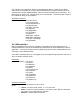
The “channels” and “gains” arrays are replaced with “channelsPacked” and “gainsPacked”. The
OCX has a function “FourPack” (4.23) which will convert 4 elements to a packed value. The
packed value is determined as: element[0] + (element[1] * 2^8) + (element[2] * 2^16) +
(element[3] * 2^24).
The parameters “demo”, “ledOn”, “disableCal”, “transferMode”, “updateIO”, and “stateIOin”, are
replaced by an “optionBits” parameter. Call the OCX function “BuildOptionBits” (4.22) to
determine this parameter.