
User Manual
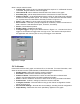
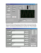
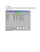
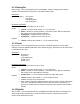
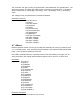
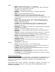
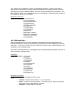

Figure 3-12. LJstream
Figure 3-13 shows the LJstream channel configuration window. Here you can select analog
inputs and gains and enter scaling equations. Use “Test Data” to see the effect of the scaling
equations (“v” column is the measured voltage and the “y” column is the output of the scaling
equations). “Manual/Sampled” determines where the “Test Data” in the “v” column originates.
Figure 3-13. LJstream Channel Configuration