
User Manual
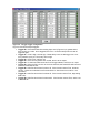
sampleRate = scanRate * numChannels
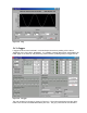
AIStreamRead is called periodically during a stream acquisition started by AIStreamStart. Each
call retrieves multiple samples of 1-4 channels from the LabJack stream buffer, along with the
states of the IO pins (read every 4 samples). Hardware-timed sample rates of up 1200 Hz are
available.
2.2 AO0 & AO1
The LabJack U12 has 2 screw terminals for analog output voltages. Each analog output can be
set to a voltage between 0 and the supply voltage (+5 volts nominal) with 10-bits of resolution.
The output voltage is ratiometric with the +5 volt supply, which is generally accurate to ±5% (see
Appendix A). If an output voltage of 5 volts is specified, the resulting output will be 100% of the
supply voltage. Similarly, specifying 2.5 volts actually gives 50% of the supply voltage.
If improved accuracy is needed, measure the +5 volt supply with an analog input channel, and
the actual output voltage can be calculated. For instance, if an analog output of 2.5 volts is
specified and a measurement of +5V returns 5.10 volts, the actual output voltage is 2.55 volts.
Alternatively, the analog output can itself be measured with an analog input.
There is a 1
st
order low-pass filter on each analog output with a 3dB frequency around 22 Hz.
Each analog output on the LabJack U12 is the output of an operational amplifier. Accidental
application of an overvoltage or transient such as ESD (electro-static discharge) can damage
these amplifiers. If your application warrants additional protection, a series resistor and zener
diode to ground are recommended. A 5.6 volt zener such as the 1N4734 (Digi-Key part number
1N4734ADICT-ND) can be connected directly to the screw terminals. The thin stripe (cathode)
goes to AOx and the other lead goes to a nearby GND. One end of the series resistor connects
to AOx and the other end connects to your signal wire. The resistor should be as large as
possible (10 ohms will help, 100 ohms is good, 1k ohms is very good), taking into account the
voltage that will be dropped across the resistor.
Software
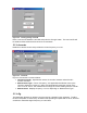
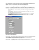
The analog outputs are set using the function EAnalogOut (easy function) or AOUpdate, which
take up to 20 ms to execute, providing a maximum update rate of about 50 Hz per channel.
AOUpdate also controls/reads all 20 digital I/O and the counter.
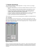
2.3 IO0 – IO3
Connections to 4 of the LabJack’s 20 digital I/O are made at the screw terminals, and are
referred to as IO0-IO3. Each pin can individually be set to input, output high, or output low.
These 4 channels include a 1.5 k Ω series resistor that provides overvoltage/short-circuit
protection. Each channel also has a 10 MΩ resistor connected to ground.
One common use of a digital input is for measuring the state of a switch as shown in Figure 2-5.
If the switch is open, IO0 reads FALSE. If the switch is closed, IO0 reads TRUE.