
User`s manual


13 Auto-initiated Response
1 Auto-initiated Response Table
Basic function and button-press of the following functions will initiate response message automatically.
Category 1 0x01=Query System Status
Data 1
USB
Inserted
SD
Inserted
0
USB
Activated
SD
Activated
Ready Busy Mode
Data 2 A -> B Program Delete Record Play Pause Stop
14 System Integration
Never use RS-232 and RS-485 Ports Simultaneously !
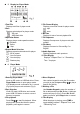
1 Connections & Control via RS-232 Port
Please use a 9-pin D-sub RS-232C cable to
connect RS-232 port on rear panel 20 P.4 to an
external controller as fig.10. Set communication
parameters as 14-3. One unit of recorder / player
can be remotely controlled via RS-232 port.
2 Connections & Control via RS-485 Port
Please use a RS-485 cable to connect RS-485
port on rear panel 21 P.4 to an external controller.
Set communication parameters as 14-3. Up to
16 units of controlled units can be controlled via
RS-485 port.
3 Serial Port Settings
After controller connections are completed, be
very sure to set serial port communication
settings of your controller as follows :
→ Baud Rate:4800
→ Parity:N
→ Data Bits:8
→ Stop Bits:1
→ Flow Control:N
4 Examples
Q1:How do I use a Crestron controller to operate
" Play " and " Stop " ?
A 1:Please refer to 10 / P.8 control commands, set
communication settings as 14-3 / P.10 and
start to send command. Recorder / Player
will react instantly upon receiving the
following codes (e.g. ID=00):
Play \xFA\xAF\x00\x02\x02\xAA\xFF
Stop \xFA\xAF\x00\x03\x03\xAA\xFF
Q 2:When I insert an SD card or a USB flash drive
to SR-101 PRO, how do I query system
status?
A 2:When Recorder / Player detects SD card or a
USB flash drive, basic response will be
initiated automatically. Please refer to 13 /
P.10 for details. System integrators may
decide to execute or ignore the automatic
response (e.g. ID=00).
SD Inserted 0xFA0xAF0x000x4C0x010xE70xFF
USB Inserted
0xFA0xAF0x000x940x010x3F0xFF
- 11 -