
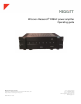
Instruction manual


Page 10 of 12
4.0 Operation
4.1 Applying power
Verify the AC voltage is correct and all necessary cables are securely
attached.
Switch the power/circuit breaker switch to the "ON" position.
Push the front panel power switch and observe the LED turning from unlit to red (mute). When the
power supply has stabilized the amplifier will come out of mute and the LED will change to green
(normal operation).
Note: If the power indicator color remains red, a fault condition exists within the power amplifier
or output circuit. Turn off the power, repeat the steps in the initial system setup (section 3.0) then
re-apply power. If the fault persists, contact Meggitt Sensing Systems. The LED, when unlit,
indicates no A/C mains power is present and the amplifier probably needs only to be powered on
or the rear panel circuit breaker is switched off.
Clipping occurs when the channel output level no longer can follow the level increase at the input
(overdriven input condition). When the PA8HF is driven into clipping the LED will change from
green to red then back to green when the level is reduced (flashing red). Momentary clipping can
be tolerated, however it indicates that maximum output power has been surpassed and potential
amplifier or shaker damage may result if overload conditions persist. Any amplifier that is
constantly operated into clipping indicates a more powerful amplifier is needed for that
application.
The PA8HF has thermal shutdown circuitry to prevent damage due to overheating. Should
thermal shutdown occur, the amplifier will mute and the LED will turn orange indicating this
condition. When the amplifier has cooled to a safe operating condition the PA8HF will return to
normal operation. Persistent thermal shutdown indicates a cooling fan may be necessary to
increase airflow across the heat sink. The end user should investigate cooling fans for this.
4.2 Test operation
Follow the procedures below to test the operation of the power amplifier.
1. Verify the amplitude level of the signal source is set to its minimum position.
2. While monitoring the shaker force output level, or acceleration level, gradually increase the
signal output level of the signal generating system.
3. Verify that the shaker force being applied to the test structure is adequate to continue testing.
4. If there is no force output from the shaker reduce the signal generating system output signal
to its minimum, turn off all power, check all instrumentation components, check all system
fuses, and check all cabling before re-applying power.
5. If it appears that there is a problem with the power amplifier, please refer to maintenance
(section 5.0) for assistance. If the shaker is producing adequate force, the system is ready to
use for testing.
6. At the completion of all testing operations, reduce the signal generating system output signal
to its minimum and turn off power to all test system components.