
User's Manual


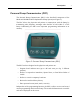

Table Of Contents
- Table of contents
- List of figures
- CHAPTER 1 Description
- CHAPTER 2 Indications and contraindications
- CHAPTER 3 Personal Pump Communicator (PPC)
- CHAPTER 4 Pump implantation
- Preprogramming and pre-testing the Pump
- CHAPTER 5 Pump refill procedure
- CHAPTER 6 Explanting the Pump System
- CHAPTER 7 Warnings and precautions
- CHAPTER 8 Adverse reactions
- CHAPTER 9 System alarms and messages
- Pump alarms
- Alarm feedback
- Pump low battery
- Depleted pump battery
- System error
- Pump self test fail
- PPC low battery
- PPC alarms
- Low reservoir
- Empty reservoir
- Telemetry communication error
- Initialize alarm
- PPC not initialized
- Battery replacement
- Initialize to factory defaults
- Pump stopped
- Pump suspended
- Auto off
- Hourly maximum exceeded
- Pump alarm table
- Pump alarms
- CHAPTER 10 Troubleshooting Pump System under-delivery
- CHAPTER 11 Technical specifications
- APPENDIX A Label information symbol dictionary
- APPENDIX B Implant worksheet
- APPENDIX C Refill form
- APPENDIX D Precautions and general procedures
- APPENDIX E Pump rinse procedure
- APPENDIX F Side Port Catheter flush procedure
- Supplies and solutions
- Preparing for the procedure
- Flushing the Side Port Catheter
- Program minimal basal rate
- Remove insulin and fill with rinse buffer
- Equilibrate and pull rinse buffer through system
- Flush side port catheter
- Remove rinse buffer and fill with insulin
- Equilibrate and pull insulin through system
- Remove guide needles and record refill amount
- Program new basal rate
- Remove rinse buffer from catheter
- APPENDIX G Stroke volume measurement

ix
List of figures
Figure 1: Implantable Insulin Pump and
Personal Pump Communicator (PPC) . . . . . . . . . . . . . . . 1
Figure 2: The Implantable Insulin Pump . . . . . . . . . . . . . . . . . . . . 3
Figure 3: Interior of the Implantable Insulin Pump . . . . . . . . . . . . 4
Figure 4: The Intraperitoneal Catheter and Side Port . . . . . . . . . . . 6
Figure 5: Personal Pump Communicator (PPC) . . . . . . . . . . . . . . . 7
Figure 6: Filling the hub of the refill needle . . . . . . . . . . . . . . . . 55
Figure 7: Venting the syringe head space . . . . . . . . . . . . . . . . . . 57
Figure 8: Testing Pump stroke volume with a pipette . . . . . . . . . 60
Figure 9: Tubing and retainer removal . . . . . . . . . . . . . . . . . . . . . 61
Figure 10: Proper attachment of the Side Port Catheter to Pump . 62
Figure 11: Example of Pump placement . . . . . . . . . . . . . . . . . . . . 65
Figure 12: Filling the hub of the refill needle . . . . . . . . . . . . . . . . 72
Figure 13: Operation of the Pump inlet valve . . . . . . . . . . . . . . . . 74
Figure 14: Venting the Medtronic MiniMed refill syringe . . . . . . 76
Figure 15: Template and placement . . . . . . . . . . . . . . . . . . . . . . . 111
Figure 16: Inlet valve . . . . . . . . . . . . . . . . . . . . . . . . . . . . . . . . . . 112
Figure 17: Venting the refill syringe . . . . . . . . . . . . . . . . . . . . . . 113
Figure 18: Stroke volume measurement setup . . . . . . . . . . . . . . . 138
Figure 19: Stroke volume measurement . . . . . . . . . . . . . . . . . . . . 139