
User Manual


GPI171-IM27 MDS86850ESKD
Revised: 04/10/2014
7
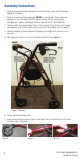
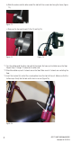
8. Insert the rear wheel assembly (Figure 6 and Figure 7) on the side facing up. Make sure that the
brake shoe (M) is toward the outside of the frame. Insert one triangular knob (L) (Figure 8).
9. Insert the handle/brake handle assembly (B and G) into the frame (Figure 9). The brake cables
should be on the outside of the handlebars and frame. Ensure excess brake cable loops towards
the front of the rollator.
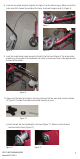
10. Align one of the holes to the hole in the frame and insert the four point knob, washer and bolt
(C) (Figure 10) to hold the handle/brake handle assembly in place.
a) Insert the bolt into the 6 sided hole in the frame (Figure 11). Make sure the bolt head
recesses into the frame (Figure 12).
Figure 6
Figure 9
Figure 7
Figure 10
Figure 8
Figure 11 Figure 12