
Hardware manual
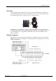
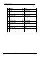
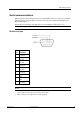
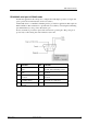
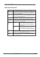
Table Of Contents
- Cover Page
- Contents
- About this guide
- Safety Instructions and safety warnings
- Before you start
- Introduction to NION
- Setting up the NION
- Introduction
- Configuration
- Updating the firmware
- Using the front panel
- Using the web interface
- Using XDAB clusters with VLANs and CobraNet
- Introduction
- Important concepts
- Use cases
- Scenario 1 - Basic network
- Scenario 2 - Network using VLAN
- Scenario 3 - Network with VLAN and analog interconnects
- Scenario 4 - Network with VLAN and digital interconnects
- Scenario 5 - Network with an XDAB cluster
- Scenario 6 - Network with VLAN and XDAB
- Scenario 7 - Network with VLAN and XDAB
- Scenario 8 - Network with VLAN and two XDAB clusters
- Scenario 9 - Network with VLAN and three XDAB clusters
- Setting conductor and XDAB priority in NWare
- Further examples
- Troubleshooting
- Connector ports
- Technical specifications
- Reference Information
- Warranty statement
Appendix B - Connector ports
80 Version 1.6.2a.0 May 17, 2011
So
me text t o force a page b reak in Word but remain inv isible
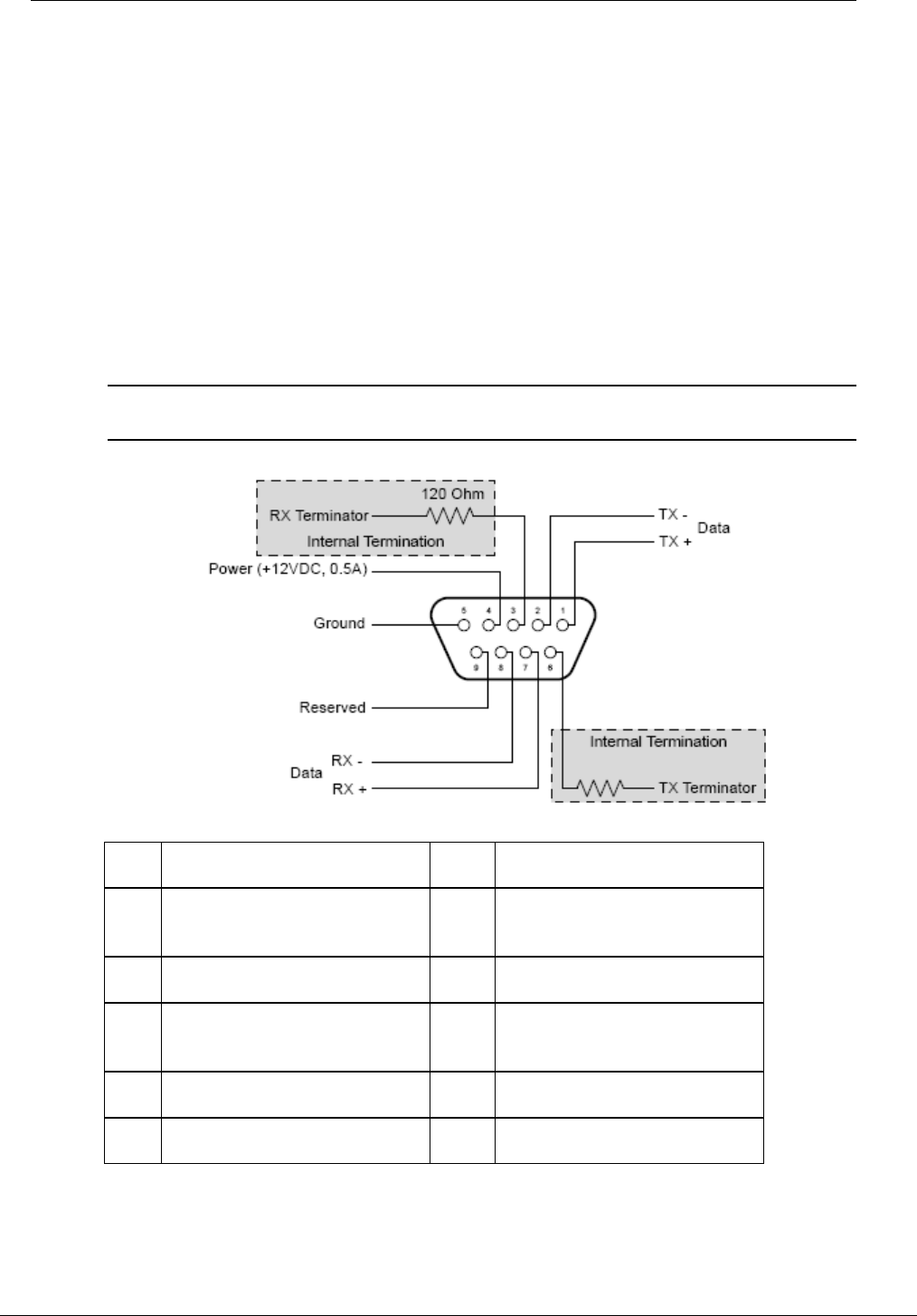
RS-422/485 serial port in RS-422 mode
Four RS-422 separate data pairs are provided for transmit (TX) and receive (RX).
Additionally, there is a 120 Ohm terminating resistor provided for each data pair for
applications that require an EOL termination. The termination is optional and is accessible by
connecting the terminating pin for each data transport pair.
To enable termination for the transmit pair, connect the terminating resistor pin (TX
Terminator) to the positive data transmit (TX+) pin.
To enable termination for the receive pair, connect the terminating resistor pin (RX
Terminator) to the positive data receive (RX+) pin.
Power (+12VDC) is provided on pin 4 and is referenced to ground, pin 5. The power pin is
protected by a self-resetting fuse and is limited to 0.5A, max.
Note: Transmit (TX) and Receive (RX) are from the point of view of the NioNode. Connect
them to the opposite port of the remote unit.
Pin Function Pin Function
1 TX Data + 6 TX 120 ohm terminating
resistor
2 TX Data - 7 RX Data +
3 RX 120 ohm terminating
resistor
8 RX Data -
4 +12 VDC (0.5A) 9 Reserved (no connection)
5 Ground