
Installation Guide
12/04/07
Revision 1.0
2 of 6
2.6 Install base plate and lock ring to secure lock cylinder to door. Install spacers
as required for thin door applications.
2.7 Place cylinder in locked position and remove the User key. User key is no
longer needed until Hybrid unit is programmed.
2.8 Ensure the battery is removed from the MCU unit.
2.9 Connect the cable from the cylinder to the back of the MCU unit.
2.10 Locate and install the MCU onto the base plate using the four mounting
screws. Care must be taken to ensure the interconnect cable is routed properly
behind MCU and is not damaged.
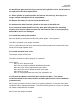
2.11 Install the battery into the MCU
MCU will power up and flash the LED red, yellow, green - one sequence.
The MCU will power up in tamper condition.
The LCU will power up and “arm” the electronic blocking mechanism (mechanical key
alone will no longer operate lock)
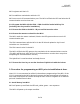
2.12 Install the MCU outer cover
The tamper switch will be reset
The MCU will start to search (ping) for a credential
At this point:
MCU is still in tamper mode
MCU has no master credential identified and stored
MCU and LCU are not registered to each other
MCU and LCU are not authorized with each other
MCU clock is not set
MCU is not programmed with a key list, schedules, etc.
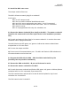
2.13 Present the Master Credential (Prox Card) to the MCU – The master
credential should be the same used for all other Hybrid locks in this installation
(customer site)
MCU reads and stores the Prox Card as its master credential – It remains the master
credential unless reprogrammed later. The LED will flash green for 3 cycles to indicate
the master credential was accepted.
MCU resets the tamper condition