
User Manual
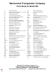

General Operating and Maintenance Instructions
REGULATING PLANT SETTING DEPTH: All new operators should take care to see that the plants are placed well down in the pockets so that the
plant is held fi rmly. The depth for setting of plants can be regulated by the distance that root is extended out of the pocket.
CHAIN UNITS: Make sure the upper conveyor sprocket isn't over tightened, causing the chain to become stretched between the upper and lower
sprockets. This will put unnecessary friction on the unit perhaps causing the packing wheels to slip on rear drive units. Tighten the wing nuts equally so
the chain runs level.
ADJUSTING AND SETTING SHOE: Whenever any adjustment is made, be sure to get the shoe directly square and straight in front of the opening of
the wheels so the pockets travel through the middle of the shoe. The shoe can be adjusted ahead or back with brace fastened on the right side of the
unit frame. In loose, dry soil, the shoe should be set back and closer to the packing wheels or ahead and away from the packing wheels in heavy, wet
soil. KEEP SHOE CLEAN at all times. Don't allow soil to build up on sides or trash in front of the shoe as this will cause the shoe to make a wider fur-
row, and the packing wheels will be unable to bring the soil back in around the plants. It may be necessary to add a coulter to the unit to cut this trash if
it's a problem. Also, make sure the soil is worked deeper than the penetrating depth of the shoe. Hard pan soil under the shoe will cause the unit to ride
up and lose its traction.
CAUTION: PULL UNIT FORWARD ONLY. Backing up causes damage to pockets and can plug shoe up with dirt.
ADJUSTING WATER VALVE: The water valve has a ball check tripped from below. The reservoir allows water supply to build up between plants.
There is a fl oat in the top of this reservoir to automatically close when fi lled. This air allows water to drop quickly as it is tripped by each plant. The
AMOUNT OF WATER IS CONTROLLED BY SIMPLY ADJUSTING THE BALL VALVE to regulate the amount of water you want by each plant. Be care-
ful, too much water in dry fl uff y soil can cause the plant to fl oat to the top of the furrow. The rocker arm and cam which is bolted onto frame of planter for
tripping valve has a slot in it for adjusting timing of water. When rocker is moved up, the water will trip sooner. When moved down, it will trip later.
AIR VALVE FLOAT: Once each season the cap at the top of valve should be removed to check condition of the air valve fl oat. This small ball can be
fl oated to the top with water or pulled out with a piece of wire for inspection. This fl oat is the critical to the operation of this valve. It and the rubber at the
top should be replaced if not in good condition.
INSTALLING NEW BOTTOM CHECK BALL: Remove the valve from planter. Then remove bottom spout and the adjustable slide on trip rod. Unscrew
plastic seat from tee. New check ball with stem can then be easily inserted. Do not tighten nut on stem completely, but leave enouph play for the ball to
wobble, allowing it to self center itself in the plastic seat.
MAKE SURE THE WATER IS DRAINED OUT OF THE VALVE AT THE END OF EACH SEASON OR IT WILL FREEZE AND DESTROY THE INSIDE
OF THE VALVE!
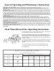
Float Wheel Direct Drive Operating Instructions
Run the fl oat wheel with only 4 to 5 pounds of pressure during operation. Plant spacing can
be changed slightly by increasing or decreasing the tire pressure.
Be sure to run the planting unit level with the soil. Then check that the toolbar is in the
middle of the hitchso that frame members #23 and #20 are STRAIGHT IN LINE. Do not run
the front frame (#20) up as this will take weight off from the wheel. For toolbars that are not
adjustable for height you may have to use the lower holes on the front clamp plates to get
the frame to run straight.
The hitch and wheel will fl oat freely and sense uneveven soiol conditions if set properly. DO
NOT TIGHTEN LIFT CHAINS. They must be loose when planting. If you can not lift the
units high enough, raise the lower arms on your tractor by cranking them up. Do not tighten
the chains.
For some unuasual spacings, an extra link or two may be added to the drive chains.
If more weight is needed on the back of the unit for proper packing, use the optional
OE-73 weight bracket.
MODEL 550 LU SPACING CHART
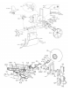
12- #1915 Pockets on a disc
Sprocket on outside
of Jackshaft
Sprocket on Inside
of Jackshaft
Number of teeth on Sprocket by Disc
11
11
11
9
8
7
5-1/2” 6” 7”
7 8 9 10 11
7-1/2” 8-1/2”
8-1/2” 9” 10”