
Manual
9
3) Maintenance
The CCU does not ‘field strip’. The main areas of concern
are lubrication and cleaning. The cleaning of the barrel bore and
chamber is performed using the same techniques as with other
firearm systems. Use a cleaning rod and a bore brush followed by
rod and patch. Use any of the commonly available bore solvents
for this. The barrel is stainless steel and does not require any
lubrication after cleaning. Lock back the bolt in the open position
while cleaning the bore. Be aware that it is possible to inadvertantly
disengage the lock back and have the bolt slam shut. Keep fingers
out of the ejection port area. Clean the breech face using a small
scrub brush or an old tooth brush using any of the commonly
available gun cleaning solvents.
The inside of the housing in the areas where the bolt slides
can be cleaned most effectively using a flush method where these
areas are sprayed with one of the commonly available aerosol type
gun solvents. Be certain to apply the flush also to the inside of the
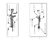
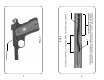
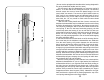
housing forward of the ejection port. The way to do this is to lock
back the bolt and hold the CCU vertically with the muzzle down.
Then apply the spray solvent at points ‘A’ on the housing(see Fig.4).
Most of the aerosol type spray solvents come with a small diam-
eter spray ‘nozzle’ tube which attaches to the container’s main
nozzle. Insert this tube in about 1/4” at point ‘A’ and pointing to-
ward the muzzle - then apply a couple of squirts into the housing.
After applying the flush solvent, hand cycle the bolt several times
while holding the CCU vertically but with the muzzle up. Repeat this
process a second time and make certain that the solvent has well
drained from the housing before applying a lubricant.
After cleaning the unit, it is necessary to apply a suitable
gun lubricant. These lubricants are also available in aerosol spray
type containers which are handy but not absolutely necessary.
Apply any of commonly available gun lubricants to the following
areas with the bolt closed:
- The outside surface of the barrel which is visible from the under-
side of the CCU. Apply to the right and left sides so as to run down
and lubricate the channel in the bolt in which the barrel rides.
- The surface of the bolt visible in the bolt handle slot on the left
side of the CCU.
- The inside surfaces of the housing immediately at the rear of
the bolt.
10
- The bolt recoil spring channel also with the CCU pointing some-
what downward. The rear of the spring channel is located at 12
o’clock on the bolt and the spring retaining ‘post’ can be seen from
the rear of the bolt with the bolt closed. Do this immediately after
the previous step and then hand cycle the bolt several times with
the CCU in a muzzle-down position.
- The rear of the bolt insert at the point where the firing pin
protrudes. Hold the unit vertically to allow lubricant to migrate into
the firing pin tunnel.
4) Disassembly/Assembly
Before beginning this exercise be certain to wear suitable eye
protection because the CCU contains spring loaded subassem-
blies. There are three major subassemblies in the CCU and these
are:
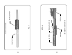
- Barrel subassembly (Fig.7)
- Bolt subassembly (Fig.9)
- Main Housing subassembly (Fig.8)
The first step in disassembly involves removing the first two
subassemblies from the inside of the main housing.
Note that the barrel and bolt subassemblies are removed simulta-
neously and are connected together by the recoil spring (Fig.6).
Care must be taken to grasp these two subassemblies as they are
withdrawn from the housing so as to insure that they stay together
until both hands are available to separate them.
To begin the removal process, remove the bolt handle. You will
need a 5/32” hex wrench to remove the bolt handle retaining screw
- a #10-32 x 1” SHCS. The bolt handle is a small subassembly
which stays with the retaining screw. This subassembly consists of
a bolt handle; a bolt handle spring; a bolt handle spring retaining clip;
a bolt handle bushing and a 10-32 x 1” socket head cap screw(SHCS).
Later CCU units have a re-designed bolt handle system which does
away with the spring and spring retaining clip. These use a longer
bushing and a 10-32 x 1 1/4” SHCS. The housing for these later
units is also re-designed relative to the later bolt handle configura-
tion. The cocking slot for the spring loaded bolt handle has a ‘dolls
head’ relief at the forward limit of the cocking slot. The later revs for
the springless bolt handles do not have the ‘dolls head’ relief. These
design variations are minor in nature and will not affect the disas-
sembly procedure at this point. Generally there should be no need
to disassemble the spring loaded bolt handle subassembly.