
Manual
19
The rotational orientation of the pins is critical. When reassembling the pins
it is important that the ‘split’ in the pins faces forward. (10mm & 460R units
have solid pins) After the pins have been driven out, the insert assembly is
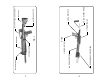
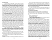
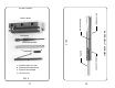
free to be removed. Note in FIG.5 the various components involved. Take
care in removing the insert and note the position of these components. The
extractor spring can fall free after the insert has been removed from the
channel.
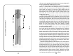
When the extractor pivot pin is removed the extractor falls free.
Note carefully how the extractor is oriented. The ‘claw’ faces in-
ward. The extractor has two small holes at one end. The rear-most
hole is larger and it is through this hole that the pivot pin must go
when reassembling. The smaller hole just forward of the pivot pin
hole is for the extractor spring. The short leg of the extractor spring
inserts into this hole while the longer leg points forward and lies
parallel to the extractor. When reassembling the insert into the bolt
channel be certain to correctly position the extractor spring as de-
scribed. The spring is caged by the bolt channel. After reassemby,
test the extractor function by pulling outward on the claw and note
that the claw returns when released. The action of the spring should
be evident.
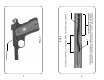
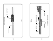
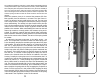
An extremely important component is the safety spring - see
FIG.9. This component is precision formed from steel spring wire.
It is a deceptively simple part considering the important role it plays
in the system. The spring is held in place by an ‘L’ bend at the front
end. The ‘L’ simply slips into a hole drilled in the bolt channel. As
shown in FIG.9 the spring is lying flat in the bolt channel with the
hairpin loop at the rear end surrounding a projection machined into
the channel. This is NOT the way it is when the channel is removed
from the unit - it is shown in FIG.9 lying flat for clarity as to how it
relates to the channel when the channel is installed in the main
housing. In reality the spring has a set in it such that when the ‘L’ is
in place in its’ hole the rear end hairpin loop is raised away from the
channel by about 1/2” - totally clearing the projection mentioned
above. Make certain to observe this when first dissasembling the
unit. The spring could actually fall free from the channel when the
channel is removed from the housing. Upon reassembly it is impor-
tant to position the spring with the loop engaging the projection as
shown in FIG.9 and hold it in this position while slipping the bolt/
barrel assembly (FIG.6) back into the housing. Once the channel is
in the housing the spring cannot escape. The function of this spring
is discussed in the ‘Operation’ section of this manual.
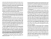
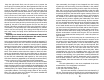
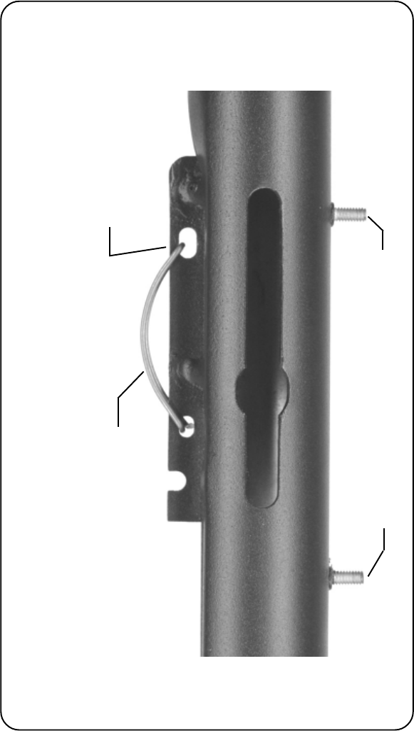
FIG. 10
MOUSETRAP SPRING
CLOSED END OF SPRING
RAIL MOUNTING THREADED STUDS
20