
Manual
15
Keep the right thumb firmly over the post so as to prevent the
recoil spring from leaving the post. Now separate the bolt from the
barrel by about 3 inches. Do this by pulling the assemblies apart
along an axis parallel to the barrel. You will notice that the recoil
spring has stretched. Carefully tilt the barrel, using your right thumb
as the approximate pivot point, so that the portion of the barrel
which is to the rear of the support moves out of the channel in the
bolt. When the barrel just clears the bolt channel, begin to relax the
recoil spring by allowing the subassemblies to come together slowly.
You will learn how to maneauver the barrel to allow complete relax-
ation of the recoil spring at which point the spring loop can be safely
slipped off the post in the barrel support and you can relax your
thumb. (This entire procedure will have to be reversed in order to
re-assemble.) The important point of the disassembly is to maintain
control over the recoil spring. If the spring should slip off the post
and ‘snap’ closed, the spring will be deformed and should not be
used again.
Hopefully one should at this poit understand why the di-
rective is given to read and understand this entire manual
before attempting disassembly of the unit.
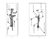
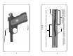
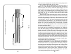
At this point the three basic subassemblies should be separated. To
review please refer first to FIG.7 which is the barrel subassembly.
Note the front buffer and be certain to have this part in position
against the support when re-assembly begins. The barrel and bar-
rel support should not be separated. These parts are assembled
using special fixtures and there should be no need to separate
them. If the situation arises where the support or barrel are dam-
aged, the subassembly should be sent intact back to the factory
for remedy. Refer now to FIG.6 which shows the barrel subassem-
bly and the bolt subassembly held together by the recoil spring.
After these have been separated by the techniques outlined above,
what is not shown in FIG.7 constitutes the bolt subassembly.
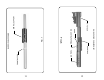
The main housing subassembly should be obvious and consists
of the tubular housing with the short sight rail on top and the black
plastic foregrip at the front. Also included in this subassembly is the
rubber recoil absorber, foregrip and whatever stock happens to be
installed (FIG.8) The rubber components are glued in place using a
cyanocylate adhesive. The foregrip simply slides off the housing.
Note: your unit may have one of several rail systems installed and
of course will differ from the photos.
16
Upon reassembly, the foregrip is best ‘snapped’ onto the housing
by placing it over the housing, from the underside, in the position
where it will be and then pressing it until it snaps over the housing.
After this it must be more precisely positioned so that the eight
holes in the foregrip align with the eight holes in the housing. It must
be perfectly aligned so that the barrel support retaining screws will
reassemble properly. Great care must be taken to avoid stripping
the threads in the barrel support during reassembly. A word is
necessary at this juncture regarding the relationship of the barrel
support retaining screws and the main housing. By close examina-
tion one can determine that the holes in the housing are larger than
the screw heads. This is by design. When properly installed, the
screw heads should come up tight against the barrel support and
not pinch the housing between the heads and the barrel support.
The barrel support is designed to ‘float’ slightly relative to the hous-
ing and the screw heads serve simply as locating pins. All of the
dynamic accelerations involved when firing the CCU are absorbed
by these screw heads and the housing holes - that is why there are
eight of them.
The sight rail on top of the housing may be removed using a nut
driver to unscrew the two #8 hex nuts located in recesses on the
top surface of the rail. Note that the rail may be assembled in either
of two positions. Which position is used is determined simply by
preferences of the operator, the optic, and eye relief required. One
position places the rail closer to the rear of the unit than the other
position. Take your pick. The hex nuts which retain the rail are
screwed onto studs which are welded to the housing tube. When
reassembling the rail do not overtighten these nuts or the stud
threads will be stripped. If the stud threads are stripped, the only
remedy is a new housing. It is a good idea to carefully examine the
completely assembled CCU before disassembly and to remember
how the parts related to each other. If your unit has another rail
system installed, follow the instructions for it when removing and re-
installing.
The bolt subassembly is the most complicated of the three
subassemblies. The components involved are:
1) the main bolt channel (FIG.9)
2) the bolt insert assembly (FIG. 5)
The bolt insert assembly is retained in the bolt channel by 3
roll pins. These pins must be carefully driven out/replaced with a 3/
16” pin punch while properly supporting the bolt in a machine vise.