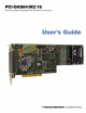
PCI-DAS64/M2/16 Multifunction Analog & Digital I/O User's Guide Document Revision 1, July, 2006 © Copyright 2006, Measurement Computing Corporation
Your new Measurement Computing product comes with a fantastic extra — Management committed to your satisfaction! Refer to www.mccdaq.com/execteam.html for the names, titles, and contact information of each key executive at Measurement Computing. Thank you for choosing a Measurement Computing product—and congratulations! You own the finest, and you can now enjoy the protection of the most comprehensive warranties and unmatched phone tech support.
Trademark and Copyright Information TracerDAQ, Universal Library, Harsh Environment Warranty, Measurement Computing Corporation, and the Measurement Computing logo are either trademarks or registered trademarks of Measurement Computing Corporation. Windows, Microsoft, and Visual Studio are either trademarks or registered trademarks of Microsoft Corporation LabVIEW is a trademark of National Instruments. CompactFlash is a registered trademark of SanDisk Corporation.
Table of Contents Preface About this User's Guide ......................................................................................................................vi What you will learn from this user's guide ........................................................................................................vi Conventions in this user's guide ........................................................................................................................vi Where to find more information ...
PCI-DAS64/M2/16 User's Guide Analog output ................................................................................................................................................. 6-7 Accuracy ........................................................................................................................................................................ 6-7 Analog output pacing and triggering.....................................................................................................
Preface About this User's Guide What you will learn from this user's guide This user's guide explains how to install, configure, and use the PCI-DAS64/M2/16 so that you get the most out of its analog, digital, and timing I/O features. This user's guide also refers you to related documents available on our web site, and to technical support resources.
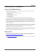
Chapter 1 Introducing the PCI-DAS64/M2/16 Overview: PCI-DAS64/M2/16 features The PCI-DAS64/M2/16 board offers a combination of high speed, channel count and resolution on a single PCI-bus data acquisition board.
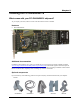
Chapter 2 Installing the PCI-DAS64/M2/16 What comes with your PCI-DAS64/M2/16 shipment? As you unpack your board, make sure each of the items shown below is included. Hardware ! PCI-DAS64/M2/16 Additional documentation In addition to this hardware user's guide, you should also receive the Quick Start Guide (available in PDF at www.mccdaq.com/PDFmanuals/DAQ-Software-Quick-Start.pdf).
PCI-DAS64/M2/16 User's Guide Installing the PCI-DAS64/M2/16 ! Signal termination and conditioning accessories MCC provides signal termination products for use with the PCI-DAS64/M2/16. Refer to the "Field wiring, signal termination and conditioning" section on page 2-7 for a complete list of compatible accessory products. Unpacking the PCI-DAS64/M2/16 As with any electronic device, you should take care while handling to avoid damage from static electricity.
PCI-DAS64/M2/16 User's Guide Installing the PCI-DAS64/M2/16 Calibrate the PCI-DAS64/M2/16 after it has warmed up and immediately before making critical measurements Use the InstaCal utility to calibrate the PCI-DAS64/M2/16 after it has fully warmed up. For best results, calibrate the board immediately before making critical measurements. The high resolution analog components on the board are somewhat sensitive to temperature.
PCI-DAS64/M2/16 User's Guide Pinout – main I/O connector Table 2-2.
PCI-DAS64/M2/16 User's Guide Installing the PCI-DAS64/M2/16 Table 2-3. 64-channel single-ended mode Signal Name LLGND CH0 IN CH1 IN CH2 IN CH3 IN CH4 IN CH5 IN CH6 IN CH7 IN CH8 IN CH9 IN CH10 IN CH11 IN CH12 IN CH13 IN CH14 IN CH15 IN LLGND CH16 IN CH17 IN CH18 IN CH19 IN CH20 IN CH21 IN CH22 IN CH23 IN CH24 IN CH25 IN CH26 IN CH27 IN CH28 IN CH29 IN CH30 IN CH31 IN D/A GND 0 D/A OUT 0 D/A GND 1 D/A OUT 1 PC +5V D/A EXTERNAL PACER EXT.
PCI-DAS64/M2/16 User's Guide Installing the PCI-DAS64/M2/16 Pins 1-50 are on the long side of the “D” connector. 50 Strain relief is stamped “Pins 1-50”. 49 50 1 2 100 Key The red stripe identifies pin # 1 99 100 1 51 Key Pins 51-100 are on the short side of the “D” connector. 51 52 Strain relief is Stamped “Pins 51-100”. The red stripe identifies pin # 51 Figure 2-1. C100HD50-x cable connections 50 100 50 100 1 51 1 51 Figure 2-2.
PCI-DAS64/M2/16 User's Guide Installing the PCI-DAS64/M2/16 Pin out – auxiliary DIO connector The auxiliary digital connector can be accessed using a variety of cabling schemes. To bring the 40-pin header out to a bracket at the back of the PC, use a BP40-37 adapter. This terminates in a CIO-DIO series compatible connector to which you can connect a CIO-MINI37 or CIO-TERMINAL screw terminal board using a C37FF-x or C37FFS-x cable.
PCI-DAS64/M2/16 User's Guide Installing the PCI-DAS64/M2/16 19 39 40 1 2 37 Key 20 1 The red stripe and arrow identify pin # 1 37-pin Male D Connector with Backplate Assembly 40-pin Female IDC Connector Figure 2-5.
PCI-DAS64/M2/16 User's Guide Installing the PCI-DAS64/M2/16 40-pin to 37-pin signal mapping Signal mapping on the C40-37F-x and the BP40-37 cables is not 1:1. Table 2-5 lists the pin numbers of the signals on the 40-pin end and the pin numbers of the associated signals on the 37-pin end. Table 2-5.
PCI-DAS64/M2/16 User's Guide 1 19 Installing the PCI-DAS64/M2/16 1 20 37 19 20 37 Figure 2-8. C37FFS-x cable Field wiring, signal termination and conditioning You can use the following accessory boards with the C100HD50-x cable. ! CIO-MINI50 — 50-pin screw terminal board. Details are available on our web site at ! SCB-50 — 50-conductor, shielded signal connection box. Details are available on our web site at www.mccdaq.com/cbicatalog/cbiproduct.asp?dept_id=102&pf_id=258. www.mccdaq.
Chapter 3 Programming and Developing Applications After following the installation instructions in Chapter 2, your board should now be installed and ready for use. Although the board is part of the larger DAS family, in general there may be no correspondence among registers for different boards. Software written at the register level for other DAS models will not function correctly with your board.
Chapter 4 Functional Description PCI-DAS64/M2/16 block diagram The PCI-DAS64/M2/16 is a multifunction measurement and control board that provides the following features: ! ! ! ! 32 differential or 64 single-ended 16-bit analog inputs Two 16-bit analog outputs 32 digital I/O channels One 16-bit counter PCI-DAS64/M2/16 functions are illustrated in the block diagram shown here.
PCI-DAS64/M2/16 User's Guide Functional Description Table 4-1 lists the input ranges and resolutions for the available input configurations and gains. Table 4-1. Analog input range and resolution configurations Bipolar Unipolar Range Resolution Range Resolution ±5 V ±2.5 V 153 µV 76.3 µV 0 to 5 V 0 to 2.5 V 76.3 µV 38.1 µV ±1.25 V ±0.625 V 38.1 µV 19.1 µV 0 to 1.25 V 19.1 µV Burst mode Channel-to-channel skew is the result of multiplexing the A/D inputs.
Chapter 5 Calibrating the PCI-DAS64/M2/16 Overview The PCI-DAS64/M2/16 provides self-calibration of the analog inputs and outputs, eliminating the need for external equipment and user adjustments. All adjustments are made via 8-bit calibration DACs which are referenced to an on-board factory-calibrated standard. The board is fully calibrated at the factory with calibration coefficients stored in nvRAM.
PCI-DAS64/M2/16 User's Guide Calibrating the PCI-DAS64/M2/16 Table 5-1. Recommended A/D calibration frequencies Calibration Frequency (kHz) Min Sampling Frequency (kHz) Max Sampling Frequency (kHz) 2 15 50 100 300 650 1250 1850 0.01 6 30 70 200 400 1000 1500 6 30 70 200 400 1000 1500 2000 For best results, calibrate the board immediately prior to making your measurements.
PCI-DAS64/M2/16 User's Guide Calibrating the PCI-DAS64/M2/16 The analog output circuits are calibrated for gain and offset. Gain calibration of the analog outputs is performed via DAC reference adjustments. Offset adjustments for the analog outputs are made in the output buffer section. The tuning range of this adjustment yields maximum DAC and output buffer offsets. The calibration scheme for the analog out section is shown in Figure 5-3.
Chapter 6 Specifications Typical for 25 °C unless otherwise specified. Specifications in italic text are guaranteed by design. Analog input Table 1.
PCI-DAS64/M2/16 User's Guide Specifications System throughput Table 2. System throughput specifications Condition Calibration coefficients Max ADC rate 1. Single channel, single input range. 2. Multiple-channel, single-input range: ±5 V, ±2.5 V, ±1.25 V, 0 to 5 V, 0 to 2.5 V 3. Multiple channel, single input range: ±0.625 V, 0 to 1.25 V 4. Single channel, multiple input ranges. Per specified range Per specified range 2.0 MS/s 1.
PCI-DAS64/M2/16 User's Guide Specifications Typical accuracy is derived directly from the various component typical errors. The information in Table 4 assumes that each of the errors contributes in the same direction. Table 5. Analog input — accuracy components specifications Range Gain error Offset error DLE ILE ±5.000 V ±2.500 V ±1.250 V ±0.625 V 0 to + 5.000 V 0 to + 2.500 V 0 to + 1.250 V ±3.0 max, ±2.0 typ ±3.0 max, ±2.0 typ ±3.0 max, ±2.0 typ ±5.0 max, ±4.0 typ ±4.0 max, ±3.0 typ ±6.
PCI-DAS64/M2/16 User's Guide Specifications Noise performance Table 8 summarizes the worst case noise performance for the PCI-DAS64/M2/16. Noise distribution is determined by gathering 50 K samples with inputs tied to ground at the user connector. Samples are gathered at the maximum specified single-channel sampling rate. Specification applies to both single-ended and differential modes of operation. Table 8. Noise performance specifications Range ±2 counts ±1 count MaxCounts LSBrms (Note 2) ± 5.
PCI-DAS64/M2/16 User's Guide Specifications Analog output pacing and triggering Table 12.
PCI-DAS64/M2/16 User's Guide Specifications Interrupts Table 14. Interrupt specifications Interrupts Interrupt enable ADC interrupt DAC interrupt sources (software-programmable) External interrupt PCI INTA# - Mapped to IRQn via PCI BIOS at boot-time Programmable through PLX9080 DAQ_ACTIVE: Interrupt is generated when a DAQ sequence is active. DAQ_STOP: Interrupt is generated when A/D Stop Trigger In is detected. DAQ_DONE: Interrupt is generated when a DAQ sequence completes.
PCI-DAS64/M2/16 User's Guide Specifications Pacer Table 16. Pacer specifications ADC pacer type Configuration ADC pacer source ADC pacer gate ADC pacer out DAC pacer type Configuration DAC pacer source DAC pacer gate DAC pacer out ASIC One down counter, 24 bits (1 scan interval, 1 sample interval) 40 MHz internal source Internally controlled by software/hardware trigger.
PCI-DAS64/M2/16 User's Guide Specifications Differential mode pin out Table 21.
PCI-DAS64/M2/16 User's Guide Specifications Single-ended mode pin out Table 22.
PCI-DAS64/M2/16 User's Guide Specifications Digital input/output connector and pin out Table 23. Digital I/O connector specifications Connector type Connector compatibility Compatible cable Compatible accessory products 40-pin header Translates to standard CIO-DIO24 type using BP40-37 C40FF-2 CIO-MINI40 Table 24.
Declaration of Conformity Manufacturer: Address: Category: Measurement Computing Corporation 10 Commerce Way Suite 1008 Norton, MA 02766 USA Electrical equipment for measurement, control and laboratory use.
Measurement Computing Corporation 10 Commerce Way Suite 1008 Norton, Massachusetts 02766 (508) 946-5100 Fax: (508) 946-9500 E-mail: info@mccdaq.com www.mccdaq.