
User Manual
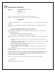

USB-1408FS User's Guide Specifications
22
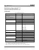
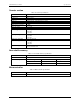
Table 7. Analog output accuracy
Range Accuracy (±LSB)
0 V to 4.096 V 4.0 typ, 45.0 max
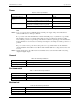
Table 8. Analog output accuracy components
Range % of FSR (±) Gain Error at FS (±mV) Offset (±mV)
(Note 6)
Accuracy at FS (±mV)
0 V to 4.096 V 0.1 typ, 0.9 max 4.0 typ, 36.0 max 1.0 typ, 9.0 max 4.0 typ, 45.0 max
Note 6: Zero-scale offsets may result in a fixed zero-scale error producing a "dead-band” digital input code
region.. In this case, changes in digital input code at values less than 0x040 may not produce a
corresponding change in the output voltage. The USB-1408FS offset error is tested and specified at
code 0x040.
Digital I/O
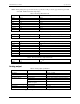
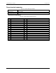
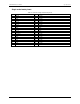
Table 9. Digital I/O specifications
Parameter Specification
Digital type CMOS
Number of I/O 16 (Port A0 through A7, Port B0 through B7)
Configuration 2 banks of 8
Pull-up/pull-down configuration All pins pulled up to 5V via 47 kΩ resistors (default).
Hardware with p/n 193331x (where x is the revision letter) may be changed to
pull-down using an internal jumper.
Other hardware versions can be configured for pull-down at the factory.
Input high voltage threshold 2.0 V min
Input high voltage limit 5.5 V absolute max
Input low voltage threshold 0.8 V max
Input low voltage limit –0.5 V absolute min
0 V recommended min
Output high voltage
(IOH = –6.0 mA)
3.84 V min
Output low voltage
(IOL = 6.0 mA)
0.33 V max
Power on and reset state Input