
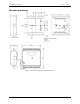
User Manual

20
Chapter 4
Specifications
All specifications are subject to change without notice.
Typical for 25°C unless otherwise specified.
Specifications in italic text are guaranteed by design.
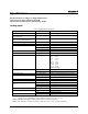
Analog input
Table 1. Analog input specifications
Parameter Conditions Specification
A/D converter type
Successive approximation type
Input voltage range for linear operation,
single-ended mode
CHx to GND ±10 V max
Input common-mode voltage range for
linear operation, differential mode
CHx to GND –10 V min, +20 V max
Absolute maximum input voltage CHx to GND ±28 V max
Input impedance 122 kΩ
Input current (Note 1) V
in
= +10 V 70 µA typ
V
in
= 0 V –12 µA typ
V
in
= –10 V –94 µA typ
Number of channels Software-selectable 8 single-ended / 4 differential
Input ranges, single-ended mode
±10 V, G=2
Input ranges, differential mode
±20 V, G=1
±10 V, G=2
±5 V, G=4
±4 V, G=5
±2.5 V, G=8
±2.0 V, G=10
±1.25 V, G=16
±1.0 V, G=20
Software selectable
Throughput (Note 2) Software paced 250 S/s typ, PC-dependent
Hardware paced 48 kS/s
Channel gain queue Up to 16 elements Software configurable channel, range, and gain
Resolution (Note 3) Differential 14-bits, no missing codes
Single-ended 13-bits
Integral linearity error
±2 LSB typ
Differential linearity error
±0.5 LSB typ
Absolute accuracy long term drift
(Note 4)
±20 V range ±3LSB typ (Δt = 1000 hr)
±4 V range ±6LSB typ (Δt = 1000 hr)
±1 V range ±8LSB typ (Δt = 1000 hr)
2.5VREF accuracy (pin 16) ±36.25 mV max
2.5VREF output current (pin 16) Source 5 mA max.
Sink 20 µA min, 100 µA typ
Trigger source Software-selectable External digital: TRIG_IN
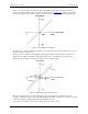
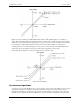
Note 1: Input current is a function of applied voltage on the analog input channels. For a given input
voltage, V
in
, the input leakage is approximately equal to (8.181*V
in
– 12) µA.
Note 2: Maximum throughput scanning to PC memory is machine dependent.
Note 3: The ADS7871 converter only returns 13-bits (0 to 8192 codes) in single-ended mode.