
User Manual

USB-1408FS User's Guide Functional Details
15
If your board has user-configurable jumpers, complete the following steps to set the pull-up/down
configuration:
1. Unplug the device from the computer.
2. Turn the device over and rest the top of the housing on a flat, stable surface.
Caution! The discharge of static electricity can damage some electronic components. Before removing the
USB-1408FS from its housing, ground yourself using a wrist strap or touch the computer chassis
or other grounded object to eliminate any stored static charge.
3. Remove the three screws from the bottom of the device using a #1 Philips head screwdriver.
4. Hold both the top and bottom sections together, turn the device over and rest it on the surface, then
carefully remove the top section of the case to expose the circuit board.
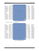
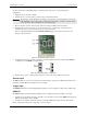
The user-configurable jumpers are labeled
DIO A and DIO B. Figure 9 shows the location of the each
jumper on the circuit board.
Figure 9. Pull-up/down jumper locations
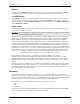
5. Configure each jumper for pull-up or pull-down, as shown in Figure 10. Use the jumper labeled DIO A to
configure Port A, and
DIO B to configure Port B.
Figure 10. Pull-up/down jumper configuration
6. Replace the top section of the housing, and fasten it to the bottom section with the three screws.
Counter input
The CTR terminal is a 32-bit event counter that can accept frequency inputs up to 1 MHz. The internal counter
increments when the TTL levels transition from low to high.
Trigger input
The TRIG_IN terminal is an external digital trigger input that you can configure for either rising or falling edge.
SYNC I/O
The SYNC terminal is a bidirectional I/O signal that can be configured as an input (default) or an output.
Configure as an external clock input to externally source the A/D conversions. The
SYNC terminal supports
TTL-level input signals of up to 50 kHz.
Configure as an output to synchronize with a second USB-1408FS and acquire data from 16 channels.
Refer to Synchronized operations on page 18 for more information.