
User Manual

USB-1408FS User's Guide Functional Details
13
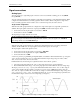
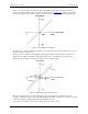
If you increase the common mode voltage to 11 V, the differential remains at ±8 V. Although the [common-
mode voltage + signal] on each input now has a range of +7 V to +15 V, both inputs still satisfy the −10 V to
+20 V input requirement (see Figure 6).
Figure 6. Differential voltage example: common mode voltage of 11 V
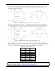
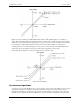
If you decrease the common-mode voltage to −7 V, the differential stays at ±8 V. However, the solution now
violates the input range condition of −10 V to +20 V. The voltage on each analog input now swings from −3V
to −11V. Voltages between −10 V and −3 V are resolved, but those below -10 V are clipped (see Figure 7).
Figure 7. Differential voltage example: common mode voltage of -7 V
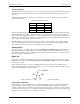
Since the analog inputs are restricted to a −10 V to +20 V signal swing with respect to ground, all ranges except
±20V can realize a linear output for any differential signal with zero common mode voltage and full scale signal
inputs. The ±20 V range is the exception. You cannot put −20 V on CHHI and 0 V on CHLO since this violates
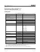
the input range criteria. The following table shows some possible inputs and the expected results.
Sample inputs and differential results
CHHI CHLO Result
−20 V 0 V Invalid
−15 V +5 V Invalid
−10 V 0 V −10 V
−10 V +10 V −20 V
0 V +10 V −10 V
0 V +20 V −20 V
+10 V −10 V +20 V
+10 V 0 V +10 V
+15 V −5 V +20 V
+20 V 0 +20 V
For more information on analog signal connections
For more information on single-ended and differential inputs, refer to the Guide to Signal Connections (this
document is available on our web site at www.mccdaq.com/signals/signals.pdf)