
User Manual

USB-1408FS User's Guide Functional Details
10
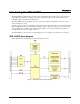
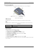
External components
The external components – screw terminal banks, LED, and USB connector –are shown in Figure 2.
1 Screw terminal pins 21 to 40 3 Screw terminal pins 1 to 20
2 LED 4 USB connector
Figure 2. External components
USB connector
The USB connector provides +5V power and communication. No external power supply is required.
LED
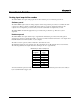
The LED indicates the communication status; it cannot be disabled. LED states are listed in the table below.
LED behavior
LED Illumination Indication
Steady green The USB-1408FS is connected to a computer or external USB hub.
Blinks continuously Data is being transferred.
Screw terminals
The screw terminals provide the following connections:
Eight analog input connections (
CH0 IN to CH7 IN)
Two analog output connections (
D/A OUT 0 to D/A OUT 1)
16 digital I/O connections (
PortA0 to Port A7, and Port B0 to Port B7)
One external trigger input (
TRIG_IN)
One SYNC I/O for external clocking and multi-unit synchronization (
SYNC)
One external event counter input (
CTR)
One voltage output (
2.5VREF)
One power output (
PC+5 V)
Five analog ground connections (
AGND) and four ground connections (GND)
Use 16 AWG to 30 AWG wire when making connections to the screw terminals. The single-ended mode pinout
is shown in Figure 3.