USB-1408FS Analog and Digital I/O User's Guide Document Revision 10 July 2014 © Copyright 2014
Your new Measurement Computing product comes with a fantastic extra — Management committed to your satisfaction! Thank you for choosing a Measurement Computing product—and congratulations! You own the finest, and you can now enjoy the protection of the most comprehensive warranties and unmatched phone tech support. It’s the embodiment of our mission: To provide data acquisition hardware and software that will save time and save money.
Table of Contents Preface About this User's Guide ....................................................................................................................... 5 What you will learn from this user's guide ......................................................................................................... 5 Conventions in this user's guide .........................................................................................................................
USB-1408FS User's Guide Microcontroller ................................................................................................................................................. 24 Power ................................................................................................................................................................ 25 General ................................................................................................................................................
Preface About this User's Guide What you will learn from this user's guide This user's guide describes the Measurement Computing USB-1408FS data acquisition device and lists device specifications. Conventions in this user's guide For more information about … Text presented in a box signifies additional information and helpful hints related to the subject matter you are reading.
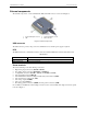
Chapter 1 Introducing the USB-1408FS The USB-1408FS is a USB 2.0 full-speed analog input and digital I/O data acquisition device supported under popular Microsoft® Windows® operating systems. It is designed for USB 1.1 ports, and was tested for full compatibility with both USB 1.1 and USB 2.0 ports. The USB-1408FS features eight analog inputs, two 12-bit analog outputs, 16 digital I/O connections, and one 32-bit external event counter.
Chapter 2 Installing the USB-1408FS What comes with your shipment? The following items are shipped with the USB-1408FS. Hardware USB-1408FS USB cable Software MCC DAQ CD Documentation In addition to this hardware user's guide, you should also receive the Quick Start Guide. This booklet provides an overview of the MCC DAQ software you received with the device, and includes information about installing the software. Please read this booklet completely before installing any software or hardware.
USB-1408FS User's Guide Installing the USB-1408FS If the LED turns off If communication is lost between the device and the computer, the device LED turns off. Disconnect the USB cable from the computer and then reconnect it. This should restore communication, and the LED should turn on. Allow the USB-1408FS to operate for at least 30 minutes before using the device. This warm up time is required to achieve the specified rated accuracy of measurements.
Chapter 3 Functional Details Analog input acquisition modes The USB-1408FS can acquire analog input data in either software-paced or hardware-paced mode. Software paced The USB-1408FS acquires data one analog sample at a time using software-paced mode. You initiate the A/D conversion by calling a software command. The analog value is converted to digital and returned to the computer. You can repeat this procedure until you have the total number of samples that you want.
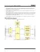
USB-1408FS User's Guide Functional Details External components The external components – screw terminal banks, LED, and USB connector –are shown in Figure 2. 1 2 Screw terminal pins 21 to 40 LED 3 4 Screw terminal pins 1 to 20 USB connector Figure 2. External components USB connector The USB connector provides +5V power and communication. No external power supply is required. LED The LED indicates the communication status; it cannot be disabled. LED states are listed in the table below.
USB-1408FS User's Guide Functional Details Figure 3. Single-ended mode pinout The differential mode pinout is shown in Figure 4. Figure 4.
USB-1408FS User's Guide Functional Details Signal connections Analog input You can connect up to eight analog input connections to the screw terminal containing pins 1 to 20 (CH0 IN through CH7 IN.) You can configure the analog input channels as eight single-ended channels or four differential channels. When configured for differential mode, each analog input has 14-bit resolution.
USB-1408FS User's Guide Functional Details If you increase the common mode voltage to 11 V, the differential remains at ±8 V. Although the [commonmode voltage + signal] on each input now has a range of +7 V to +15 V, both inputs still satisfy the −10 V to +20 V input requirement (see Figure 6). Figure 6. Differential voltage example: common mode voltage of 11 V If you decrease the common-mode voltage to −7 V, the differential stays at ±8 V.
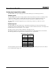
USB-1408FS User's Guide Functional Details Channel gain queue The channel gain queue feature allows you to set up a scan sequence with a unique per-channel gain setting and channel sequence. The gain settings are stored in a channel-gain queue list that is written to local memory on the device. The channel-gain queue list can contain up to 16 elements in any order. An example of a four-element list is shown in the table below.
USB-1408FS User's Guide Functional Details If your board has user-configurable jumpers, complete the following steps to set the pull-up/down configuration: 1. Unplug the device from the computer. 2. Turn the device over and rest the top of the housing on a flat, stable surface. Caution! The discharge of static electricity can damage some electronic components.
USB-1408FS User's Guide Functional Details Ground The analog ground (AGND) terminals provide a common ground for all analog channels. The ground (GND) connections provide a common ground for the digital, trigger, counter, sync and power terminals. +2.5VREF output The +2.5VREF connection is an output terminal that supplies 2.5 volts. You can use this pin as the voltage source for another analog channel. For example, to configure the +2.5VREF pin as the voltage source for channel 0 in SE mode, connect +2.
USB-1408FS User's Guide Functional Details Figure 11 shows an example of an ideal, error-free, USB-1408FS transfer function. The typical calibrated accuracy of the USB-1408FS is range-dependent, as explained in the "Specifications" chapter on page 20. We use a ±10 V range here as an example of what you can expect when performing a measurement in this range. Figure 11. Ideal ADC transfer function The offset error is measured at mid-scale. Ideally, a zero volt input should produce an output code of 8192.
USB-1408FS User's Guide Functional Details Figure 13. ADC Transfer function with gain error Figure 13 shows an example of a USB-1408FS transfer function with a calibrated gain error of ±0.02%, or ±2 mV. This means that at full scale, neglecting the effect of offset for the moment, the measurement would be within 2 mV of the actual value. Note that gain error is expressed as a ratio.
USB-1408FS User's Guide Functional Details Mechanical drawings Figure 15.
Chapter 4 Specifications All specifications are subject to change without notice. Typical for 25°C unless otherwise specified. Specifications in italic text are guaranteed by design. Analog input Table 1.
USB-1408FS User's Guide Specifications Note 4: Extrapolating the long term drift accuracy specifications will provide the approximate long term drift of the USB-1408FS intermediate input ranges. Table 2. Accuracy, differential mode Range Absolute Accuracy 25 °C (±mV) Absolute Accuracy 0 °C to 50 °C (±mV) ±20 V ±10 V ±5 V ±4 V ±2.5 V ±2 V ±1.25 V ±1 V 10.98 7.32 3.66 2.92 1.83 1.70 1.21 1.09 49.08 33.42 20.76 19.02 14.97 14.29 12.18 11.63 Table 3.
USB-1408FS User's Guide Specifications Table 7. Analog output accuracy Range Accuracy (±LSB) 0 V to 4.096 V 4.0 typ, 45.0 max Table 8. Analog output accuracy components Range % of FSR (±) Gain Error at FS (±mV) 0 V to 4.096 V 0.1 typ, 0.9 max 4.0 typ, 36.0 max Offset (±mV) (Note 6) 1.0 typ, 9.0 max Accuracy at FS (±mV) 4.0 typ, 45.0 max Note 6: Zero-scale offsets may result in a fixed zero-scale error producing a "dead-band” digital input code region..
USB-1408FS User's Guide Specifications External trigger Table 10. External digital trigger specifications Parameter Conditions Specification Trigger source Trigger mode External, digital Software-selectable TRIG_IN Edge sensitive: user configurable for CMOS compatible rising or falling edge 10 µs max 1 µs min Schmitt trigger, 47 kΩ pull-down to ground 1.01 V typ 0.6 V min 1.5 V max 2.43 V typ 1.9 V min 3.1V max 5.5 V absolute max 1.42 V typ 1.0 V min 2.0 V max -0.
USB-1408FS User's Guide Specifications Counter section Table 12. Counter specifications Parameter Pin name Counter type Number of channels Input type Input source Resolution Maximum input frequency Specification CTR Event counter 1 Schmitt trigger, 47 kΩ pull-down to ground CTR screw terminal 32 bits 1 MHz High pulse width Low pulse width Schmitt trigger hysteresis 500 ns min 500 ns min 1.01 V typ 0.6 V min 1.5 V max 2.43 V typ 1.9 V min 3.1V max 5.5 V absolute max 1.42 V typ 1.0 V min 2.0 V max -0.
USB-1408FS User's Guide Specifications Power Table 15. Power specifications Parameter Supply current (Note 7) +5V USB power available (Note 8) Output current (Note 9) Conditions Specification Connected to self-powered hub Connected to externally-powered root port hub Connected to bus-powered hub Connected to self-powered hub Connected to externally-powered root port hub Connected to bus-powered hub 80 mA 4.5 V min, 5.25 V max 4.1 V min, 5.
USB-1408FS User's Guide Specifications Screw terminal connector Table 19. Screw terminal specifications Parameter Specification Connector type Wire gauge range Screw terminal 16 AWG to 30 AWG Differential mode pinout Table 20. 4-channel differential mode pinout Pin 1 2 3 4 5 6 7 8 9 10 11 12 13 14 15 16 17 18 19 20 Signal Name CH0 IN HI CH0 IN LO AGND CH1 IN HI CH1 IN LO AGND CH2 IN HI CH2 IN LO AGND CH3 IN HI CH3 IN LO AGND D/A OUT 0 D/A OUT 1 AGND +2.
USB-1408FS User's Guide Specifications Single-ended mode pinout Table 21. 8-channel single-ended mode pinout Pin 1 2 3 4 5 6 7 8 9 10 11 12 13 14 15 16 17 18 19 20 Signal Name CH0 IN CH1 IN AGND CH2 IN CH3 IN AGND CH4 IN CH5 IN AGND CH6 IN CH7 IN AGND D/A OUT 0 D/A OUT 1 AGND +2.
Declaration of Conformity Manufacturer: Address: Category: Measurement Computing Corporation 10 Commerce Way Suite 1008 Norton, MA 02766 USA Electrical equipment for measurement, control and laboratory use.
Measurement Computing Corporation 10 Commerce Way Suite 1008 Norton, Massachusetts 02766 (508) 946-5100 Fax: (508) 946-9500 E-mail: info@mccdaq.com www.mccdaq.