
User Manual


USB-2408 Series User's Guide Functional Details
18
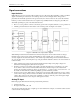
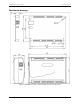
Figure 11. Location of J6 jumper
Figure 12 shows the jumper configured for pull-up and pull-down.
Figure 12. J6 jumper configurations
6. Replace the top section of the case, and fasten it to the bottom section with the four screws. Replace the
rubber feet.
For more information about digital signal connections
For general information about digital signal connections and digital I/O techniques, refer to the Guide to DAQ
Signal Connections (available on our web site at www.mccdaq.com/signals/signals.pdf).
The pull-up/pull-down voltage is common to all of the internal 47 kΩ resistors.