
User Manual


10
Chapter 3
Functional Details
External components
USB-2408 Series devices have the following external components:
USB connector
LEDs
Screw terminals
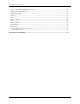
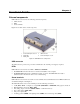
Figure 2 shows the location of each component.
1
Screw terminal pins 23 to 44
4
USB Connector
2
Status LED
5
Screw terminal pins 1 to 22
3
Activity LED
Figure 2. USB-2408 Series components
USB connector
The USB connector provides 5 V power and communication. No external power supply is required.
LEDs
USB-2408 Series devices have two LEDs – STATUS and ACTIVITY.
The Status LED is lit when the device is detected and installed on the computer.
The Activity LED indicates the communication status of a device. This LED blinks when data is
transferred, and is off when the device is not communicating.
Screw terminals
USB-2408 Series devices have two banks of screw terminals. Screw terminal functions for DIFF and SE modes
are identified in Figure 4 and Figure 3.
The USB-2408 Series device screw terminals provide the following connections:
16 SE (CH0 to CH15 – see Figure 3) or eight DIFF (CH0H/CH0L to CH7H/CH7L) analog input connections
Eight digital I/O connections (DI00 to DI07)
Two analog output connections (AOUT0, AOUT1) – USB-2408-2AO only
Two counter inputs (CTR0, CTR1)
One power output (+5V)
10 analog grounds (AGND), four digital grounds (DGND), and one chassis ground (CHAS)